A casing-less switch reluctance traction machine

A technology of switched reluctance and traction machine, applied in the direction of electromechanical devices, mechanical energy control, electrical components, etc., can solve the problems of inconvenient installation and use, high production cost, and large noise pollution, and achieve simple structure, low cost, The effect of less environmental pollution

Active Publication Date: 2017-06-13
WEIBO ELEVATOR
View PDF10 Cites 0 Cited by
  • Summary
  • Abstract
  • Description
  • Claims
  • Application Information

AI Technical Summary

Problems solved by technology

[0006] 1. Large volume and heavy weight;
[0007] 2. The structure is complex and the production cost is high;
[0008] 3. Inconvenient to install and use;
[0009] 4. High noise pollution

Method used


Image

  • A casing-less switch reluctance traction machine
  • A casing-less switch reluctance traction machine
  • A casing-less switch reluctance traction machine

Examples


Embodiment Construction

[0030] The best embodiment of the present invention will be further described in detail below.

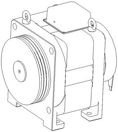
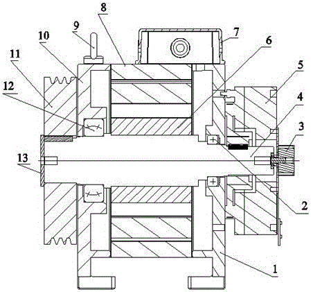
[0031] Such as Figure 1~2 As shown, the switch reluctance traction machine without casing mainly includes an end cover A1, a rotor shaft 4, a rotor core 6, a stator core 8, an end cover B10, and a traction wheel 11. The rotor shaft 4 The middle part is connected to the rotor core 6 through the synchronous shaft of the flat key. One side of the rotor core 6 is provided with an end cover A1 which is axially connected to the rotor shaft 4 through a deep groove ball bearing 2. A brake 5 is provided outside the end cover A1. The brake 5 is locked at the end of the rotor shaft 4 by a flat key, and the outer side of the brake 5 is locked by bolts to the encoder 3, and the encoder 3 rotates synchronously with the rotor shaft 4; The sub-bearing 12 is axially connected to the end cover B10 on the rotor shaft 4, and the outer side of the end cover B10 is provided with a traction sheave 11, ...


PUM


Abstract

The invention discloses a switch reluctance traction machine without a casing, which mainly includes an end cover A, a rotor shaft, a rotor iron core, a stator iron core, an end cover B, and a traction wheel. The middle part of the rotor shaft is synchronously connected to the rotor Iron core, one side of the rotor core is provided with an end cap A which is axially connected to the rotor shaft through a deep groove ball bearing; the other side of the rotor core is provided with an end cover A which is axially connected to the rotor shaft through a self-aligning roller bearing Cover B, a traction sheave is arranged outside the end cover B; the stator core is fixed between the end cover A and the end cover B, and the stator core seals the rotor core inside, and the stator core and the rotor There are gaps between the iron cores. The utility model has the advantages of simple structure, convenient installation and use, low cost and no noise pollution.

Description

technical field [0001] The invention belongs to the technical field of power equipment, and in particular relates to a casing-less switched reluctance traction machine used for elevators and the like. Background technique [0002] The traction machine is mainly divided into a gear traction machine and a gearless traction machine. [0003] Geared traction machine: The power of the dragging device is transmitted to the traction wheel through the intermediate reducer. The reduction box in it usually adopts worm gear transmission (helical gear transmission is also used). This traction machine uses There are AC and DC motors, and they are generally used in low-speed elevators and high-speed elevators. The drag ratio is typically 35:2. Generally used for low and medium speed elevators below 0.4m / s. [0004] Gearless traction machine: The power of the traction device is directly transmitted to the traction wheel without an intermediate reducer. In the past, most of these tracti...

Claims


Application Information

Patent Timeline
Patent Type & Authority Patents(China)
IPC IPC(8): H02K7/10B66B11/04
Inventor 林云发杨志闳姚逸峰许则春庄奕君余红飞
Owner WEIBO ELEVATOR
Why Eureka
Try Eureka