Discharging and dedusting device on bunker

A technology of dust removal device and ore tank, which is applied in the separation of dispersed particles, chemical instruments and methods, and filtration of dispersed particles, etc., can solve the problems of inability to open and close normally, the air volume of dust removal is not large, and the system cannot extract wind and dust, and achieve equipment operation. High efficiency, good filtration efficiency, and the effect of improving the working environment of workers

Inactive Publication Date: 2013-08-07
安徽华龙环保技术工程有限公司
View PDF4 Cites 14 Cited by
  • Summary
  • Abstract
  • Description
  • Claims
  • Application Information

AI Technical Summary

Problems solved by technology

[0002] At present, the unloading and dust removal system on the mine trough usually adopts an exhaust point at the edge of each mine trough, and each exhaust point is switched with the valve for unloading the mobile trolley, and then the centralized dust removal pipeline is used to lead to the dust removal station for centralized dust removal. The advantage is that the dust removal air volume is not large, but due to the large number of valves, the frequent opening and closing, the daily maintenance workload is heavy, the valves are prone to failure, and cannot be opened and closed normally, resulting in a relatively reduced air volume at each ventilation point, and a decline in the dust collection effect. The pipeline is long, dust is easy to deposit in the air duct, and the pipeline is blocked, resulting in the system not being able to ventilate and suppress dust, and the system consumes a lot of energy
The dust collection hood is far away from the dusting point, the trough is not tightly sealed, and the air leakage rate is high, which requires a large air volume of the system, and it is difficult to achieve the ideal effect with conventional air volume.

Method used


Image

  • Discharging and dedusting device on bunker

Examples


Embodiment Construction

[0010] The present invention will be further described below in conjunction with specific examples.

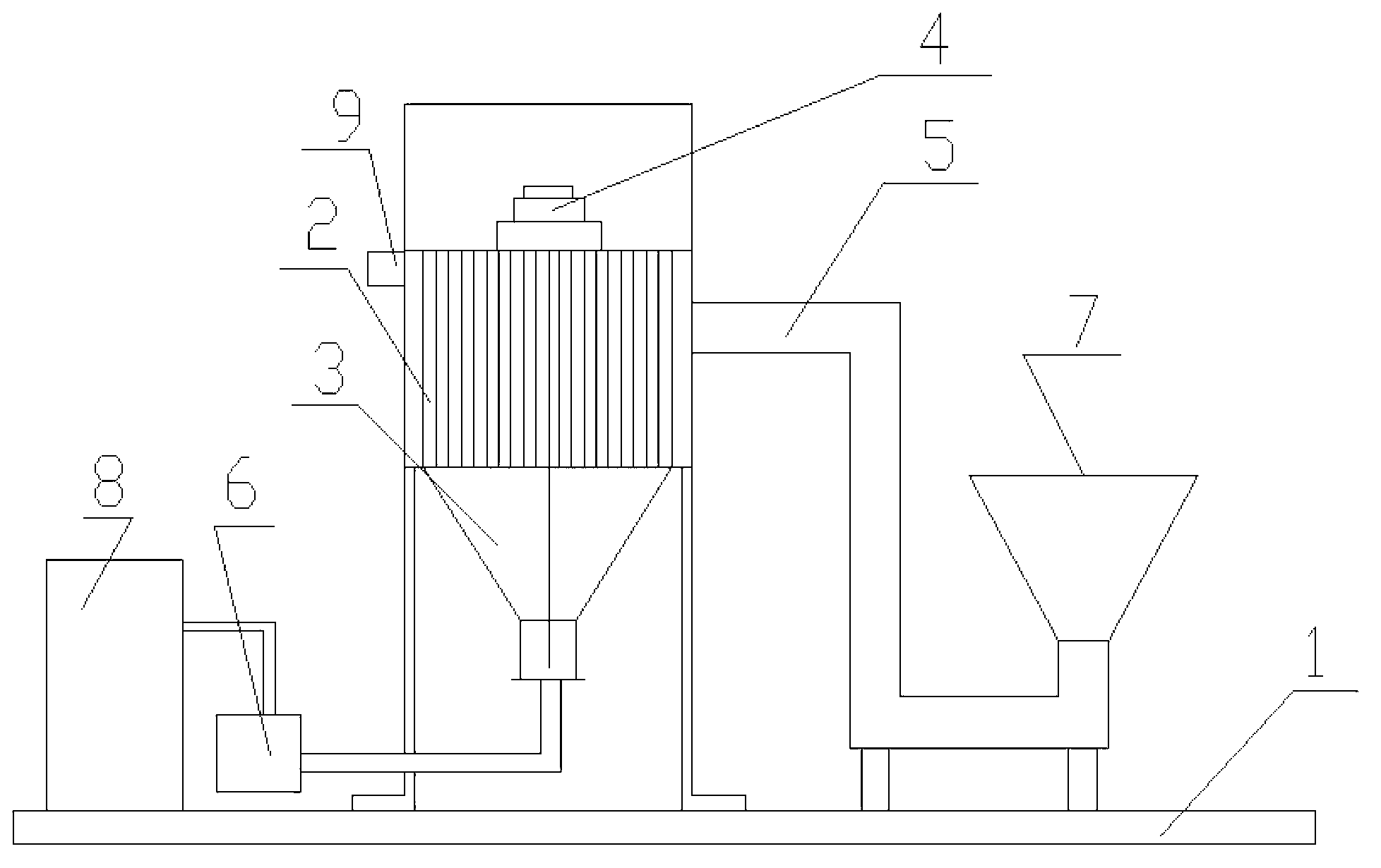
[0011] like figure 1 As shown, the unloading and dedusting device on a mine tank of the present invention includes a mobile unloading car, guide rails, and the guide rails are installed on both sides of the mobile unloading car in parallel, and the mobile unloading car is placed on the guide rails by wheels. A support platform 1 is set on the feeder, and the support platform 1 is equipped with a bag filter 2, a dust collecting bucket 3, a sonic cleaner 4, a dust removal pipeline 5, and a centrifugal fan 6, and the dust collecting bucket 3 is set on the bag filter 2, the sonic dust cleaner 4 is set above the bag filter 2, the centrifugal fan 6 communicates with the lower part of the dust collecting bucket 3 through a pipeline, and one end of the dust removal pipeline 5 is provided with an ash suction port 7, which is connected with the mobile unloading truck. The ash outlet is...


PUM


Abstract

The invention discloses a discharging and dedusting device on bunker, which comprises a movable unloading trailer and a supporting platform, and the supporting platform is arranged with a cloth bag deduster, a flue-dust retainer, a sound wave ash removing device, a dedusting pipeline and a centrifugal blower fan; the flue-dust retainer is arranged below the cloth bag deduster, and the sound wave ash removing device is arranged above the cloth bag deduster, and the centrifugal blower fan and the flue-dust retainer are communicated, and one end of the dedusting pipeline is provided with an ash suction port which is communicated with an ash outlet of the movable unloading trailer, and the other end of the dedusting pipeline is communicated with the upper part of the cloth bag deduster. When discharging, primary air containing dust enters into a deduster casing from an air inlet of the cloth bag deduster, and an outer filter cloth filters the dust in the primary air containing dust, and the dust adheres to the cloth bag; when the set value is reached, the sound wave ash removing device starts for vibrating and beating the dust which is adhered to the cloth bag, and dust drops into the flue-dust retainer, and is sent to an electric ash discharging and storing apparatus by the centrifugal blower fan for carrying away. The equipment has the advantages of high work efficiency, good filtering efficiency, improved work environment, thereby realizing energy saving and emission reduction without secondary pollution.

Description

technical field [0001] The invention relates to the technical field of environmental protection equipment, in particular to a material-discharging and dust-removing device on a mining tank. Background technique [0002] At present, the unloading and dust removal system on the mine trough usually adopts an exhaust point at the edge of each mine trough, and each exhaust point is switched with the valve for unloading the mobile trolley, and then the centralized dust removal pipeline is used to lead to the dust removal station for centralized dust removal. The advantage is that the dust removal air volume is not large, but due to the large number of valves, the frequent opening and closing, the daily maintenance workload is heavy, the valves are prone to failure, and cannot be opened and closed normally, resulting in a relatively reduced air volume at each ventilation point, and a decline in the dust collection effect. The pipeline is long, dust is easy to deposit in the air duc...

Claims


Application Information

Patent Timeline
Patent Type & Authority Applications(China)
IPC IPC(8): B01D46/04B01D46/48
Inventor 权岚
Owner 安徽华龙环保技术工程有限公司
Why Eureka
Try Eureka