Slag blocking sprue for casting

A slag blocking gate and gate technology, which is applied to casting molding equipment, casting molds, casting mold components, etc., can solve the problems of low production efficiency, entering the gap, and the gate losing the slag blocking function, etc., and achieves high production efficiency. The effect of improving efficiency

Active Publication Date: 2013-08-07
RIYUE HEAVY IND
View PDF7 Cites 6 Cited by
  • Summary
  • Abstract
  • Description
  • Claims
  • Application Information

AI Technical Summary

Problems solved by technology

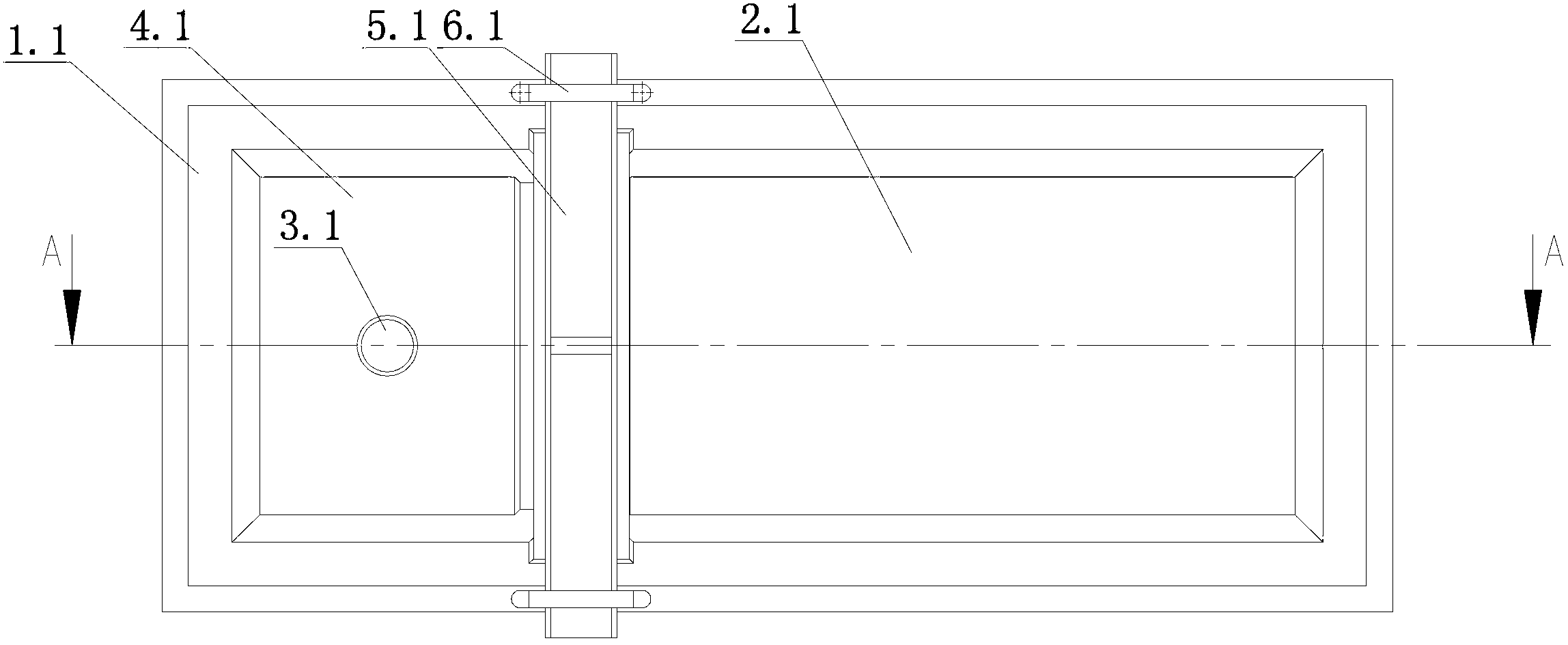
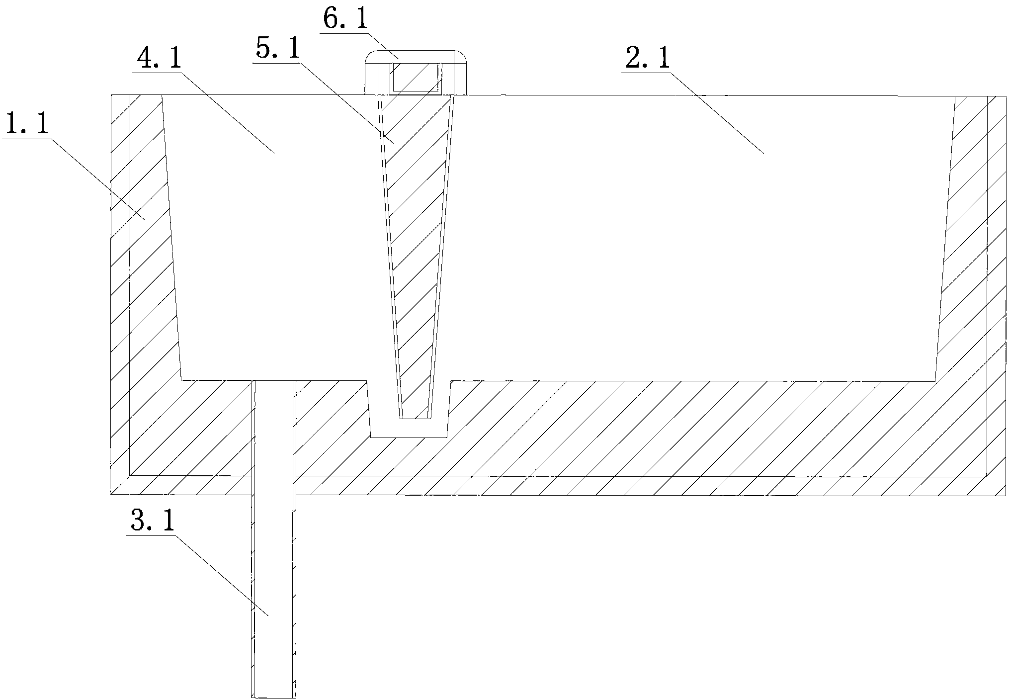
[0002] figure 1 , 2 Shown is the slag blocking gate for casting in the prior art, which is a split type or assembly type, that is, a slag blocking piece 5.1 is used to separate the inside of the gate body 1.1 into a pouring cavity 2.1 and a flow connected to the sprue 3.1. Cavity 4.1, slag stop piece 5.1 is fixedly connected with gate main body 1.1 through fixing device 6.1, such casting slag stop gate has the following disadvantages: 1. The production efficiency is low, that is, the gate body and slag stop piece need to be made separately first , Fixing device, after completion, assemble the slag blocking piece into the main body of the gate, and then fix it with the fixing device; 2. After the gate main b

Method used


Image

  • Slag blocking sprue for casting
  • Slag blocking sprue for casting
  • Slag blocking sprue for casting

Examples


Embodiment Construction

[0016] The present invention will be further described below in conjunction with accompanying drawing.

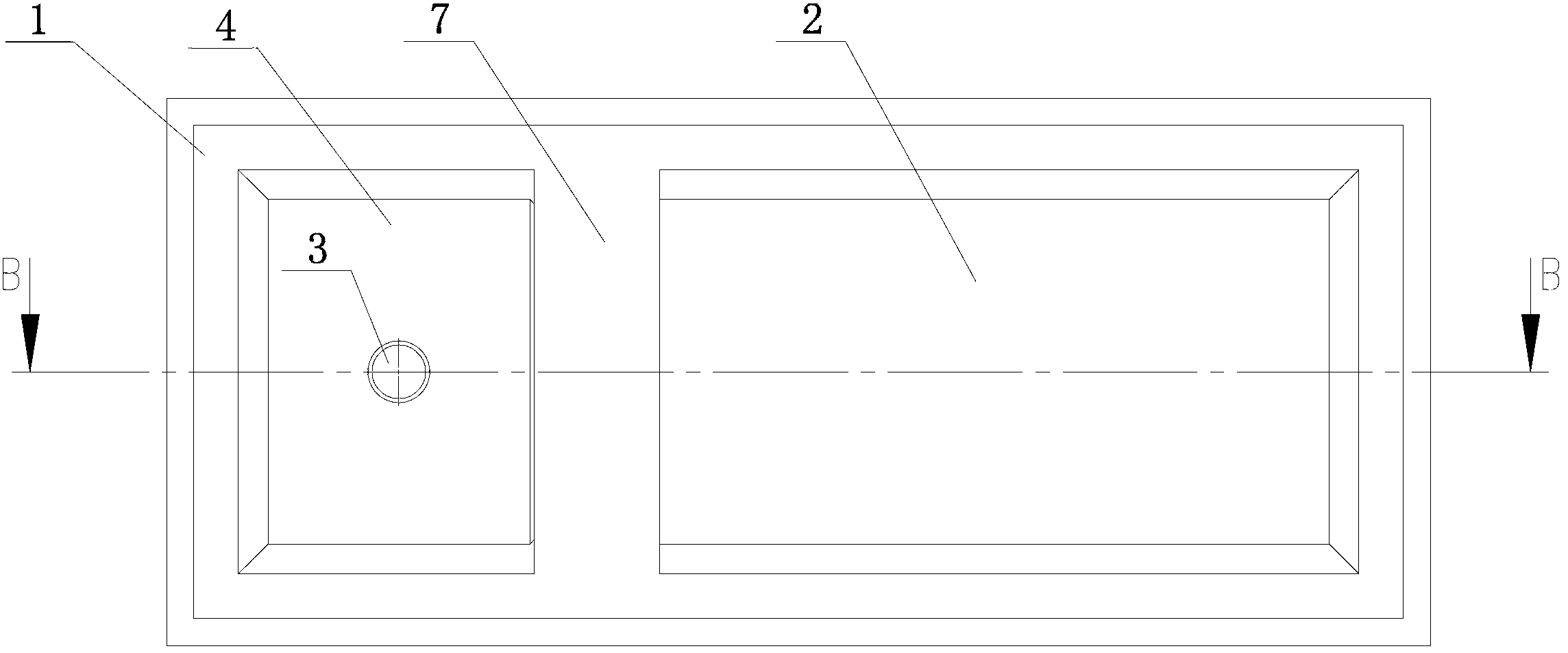
[0017] The slag blocking gate for casting of the present invention includes a gate main body 1, a groove arranged along the width direction of the gate main body 1 is provided at the bottom of the gate main body 1, and a partition integral with the gate main body 1 is provided above the bottom of the groove. The plate part 7 and the partition part 7 divide the inside of the gate body 1 into the pouring cavity 2 and the inflow cavity 4 connected with the sprue 3. At least one circulation unit 8 is buried between the partition part 7 and the bottom of the groove Each circulation unit 8 is distributed sequentially along the length direction of the groove to separate the groove into a first drainage groove 9 and a second drainage groove 10, and each circulation unit 8 is provided with a connection for communicating with the first drainage groove 9 and the second drainage groove ...


PUM


Abstract

The invention discloses a slag blocking sprue for casting, which is high in manufacturing efficiency, can not cause waste of iron liquor, does not need additional fixed devices and can not lose the slag-blocking action in casting. The slag blocking sprue comprises a sprue main body (1), wherein the bottom part of the sprue main body (1) is provided with a groove which is arranged along the width direction of the sprue main body (1); a baffle part (7) which is integrated with the sprue main body (1) is arranged above the bottom part of the groove; at least one flowing unit (8) is buried between the baffle part (7) and the bottom part of the groove; all the flowing units (8) are provided with flowing holes (11) for communicating a first flow guiding groove (9) and a second flow guiding groove (10); the adjacent flowing units (8) are attached or a gap for flowing of the iron liquid is arranged between the adjacent flowing units (8); and the flowing units (8) are used for controlling the flowing rate of the iron liquid from the first flow guiding groove (9) to the second flow guiding groove (10).

Description

technical field [0001] The invention relates to the technical field of casting, in particular to a slag blocking gate for casting. Background technique [0002] figure 1 , 2 Shown is the slag blocking gate for casting in the prior art, which is a split type or assembly type, that is, a slag blocking piece 5.1 is used to separate the inside of the gate body 1.1 into a pouring cavity 2.1 and a flow connected to the sprue 3.1. Cavity 4.1, slag stop piece 5.1 is fixedly connected with gate main body 1.1 through fixing device 6.1, such casting slag stop gate has the following disadvantages: 1. The production efficiency is low, that is, the gate body and slag stop piece need to be made separately first , Fixing device, after completion, assemble the slag blocking piece into the main body of the gate, and then fix it with the fixing device; 2. After the gate main body and the slag blocking piece are assembled together, there There are still gaps in the matching part of the gate,...

Claims


Application Information

Patent Timeline
IPC IPC(8): B22C9/08
Inventor 刘建东徐兰奎陈建军
Owner RIYUE HEAVY IND
Why Eureka
Try Eureka