Floor with multifunctional grooves in upper surface

A multi-functional, floor technology, applied in the direction of floors, buildings, building structures, etc., can solve the problems of inconvenient assembly, single function, poor anti-skid effect, etc. Effect

Active Publication Date: 2013-08-07
财纳福诺木业(中国)有限公司
View PDF12 Cites 6 Cited by
  • Summary
  • Abstract
  • Description
  • Claims
  • Application Information

AI Technical Summary

Problems solved by technology

[0008] The invention provides a floor that does not produce glue blocks protruding from the floor surface in the process of gluing, has high utilization rate of glue, good anti-slip effect, and has a massaging effect. The upper surface is provided with multifunctional grooves. , which solves the problems that the existing floor structure cannot effectively remove the rubber blocks protruding from the floor surface produced during the bonding process, the user is inconvenient to assemble, the anti-skid effect is poor, and the function is single

Method used


Image

  • Floor with multifunctional grooves in upper surface
  • Floor with multifunctional grooves in upper surface
  • Floor with multifunctional grooves in upper surface

Examples


Embodiment 1

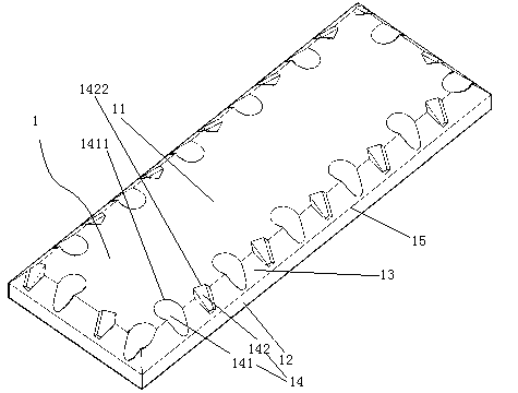
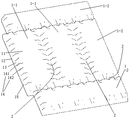
[0028] Embodiment one, see figure 1 , a floor with multifunctional grooves on the upper surface, including a middle base plate 1 . A chamfered surface 13 is provided between the upper surface 11 of the substrate and the side surface 12 of the substrate. The chamfered surface 13 is provided with several pits 14 distributed along the length direction of the chamfered surface. The recess 14 extends to the upper surface 11 of the substrate. The lower edge of the recess 14 is located above the boundary line 15 between the chamfered surface and the side surface of the substrate. The dimples 14 include several first dimples 141 and several second dimples 142 . The edge line 1411 at the opening end of the first pit is formed by connecting arc segments sequentially from end to end. The edge line 1421 at the opening end of the second pit is surrounded by straight line segments connected first and last. The opening area of ​​the first pit 141 is larger than the opening area of ​​the...

Embodiment 2

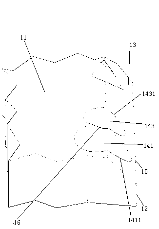
[0030] Embodiment two, see image 3 , the difference from the first embodiment is that a third pit 143 is provided beside the first pit 142 . The shape of the opening of the third pit 143 is the same as that of the first pit. The opening area of ​​the third pit 143 is smaller than the opening area of ​​the first pit 141 . The edge line 1411 of the opening end of the first pit and the edge line 1431 of the opening end of the third pit overlap together. The extrusion opening 16 is formed between the pits where the edge lines of the opening ends overlap.

Embodiment 3

[0031] Embodiment three, see Figure 4 , the difference from the first embodiment is that all the pits 14 have the same opening shape and opening area. The wall 144 of the pit is provided with a plurality of grooves 3 distributed along the circumference of the pit and extending along the depth direction of the pit. The trench 3 extends to the upper surface 11 of the substrate. The width of the upper end of the groove 3 is large, and the width of the lower end is small. Adjacent grooves meet together to form a meeting line 145 . The junction line 145 extends to the upper surface 11 of the substrate.


PUM


Abstract

The invention relates to a floor, in particular to a floor with multifunctional grooves in the upper surface. The floor comprises a plurality of baseplates, wherein beveling surfaces are arranged between upper surfaces and side surfaces of the baseplates; concave pits are formed on the beveling surfaces in the length direction of the beveling surfaces; and the beveling surfaces of adjacent baseplates form the grooves on the upper surface of the floor. According to the invention, the floor provided by the invention can avoid protruding glue blocks on the surface of the floor in the assembly process through gluing, is high in glue utilization rate and good in anti-slip effect, has a massage function, and solves the problems that the protruding glue blocks on the floor surface in the assembly process through gluing can not be effectively eliminated for a current floor structure, inconvenience is brought for users for assembly, the anti-slip effect is bad and the function is simplex.

Description

technical field [0001] The invention relates to a floor, in particular to a floor with multifunctional grooves on the upper surface. Background technique [0002] The floor is spliced ​​by substrates, and the substrates have structural forms such as strips and squares. [0003] In the Chinese patent No. ZL02291689X, the authorized public date is December 31, 2003, and the patent document named "network elevated floor" discloses a floor with a square base plate. The floor in this patent consists of a number of raised floor units, side cover panels joining adjacent edges of adjacent raised floor units together, a central cover panel connecting adjoining points of an even number of raised floor units together, and a connection of support cover panels base. The elevated floor unit includes a support frame and spliced ​​square base plates arranged on the support frame. When the base plates are spliced ​​together to form a floor, the sides of adjacent base plates are completely ...

Claims


Application Information

Patent Timeline
Patent Type & Authority Applications(China)
IPC IPC(8): E04F15/02
Inventor 曾志文白涛默
Owner 财纳福诺木业(中国)有限公司
Why Eureka
Try Eureka