Ejecting pipe

An ejector tube and cross-section technology, applied in the ejector tube field, can solve the problems of uneven flame length, influence the primary air coefficient, influence the ejection efficiency, etc. The effect of shooting efficiency

Active Publication Date: 2015-07-22
NINGBO FOTILE KITCHEN WARE CO LTD
View PDF6 Cites 21 Cited by
  • Summary
  • Abstract
  • Description
  • Claims
  • Application Information

AI Technical Summary

Problems solved by technology

[0004] Traditional atmospheric burners generally use a single-nozzle injection tube, and the injection coefficient of a single nozzle is generally only about 0.45-0.65, and the flame length is uneven and weak
In order to enhance the ejection ability of the ejector pipe, burners using multi-nozzle ejector pipes have appeared on the market. The nozzle injection tubes will interfere with each other in the early stage of injection, which will affect the injection efficiency. After the gas is injected into the injection tube, it will not be fully mixed with the air entering the injection tube, which will affect the primary air coefficient and further affect the combustion of the burner. efficacy

Method used


Image

  • Ejecting pipe
  • Ejecting pipe
  • Ejecting pipe

Examples


Embodiment 1

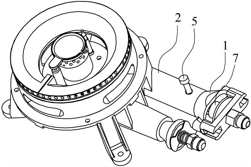
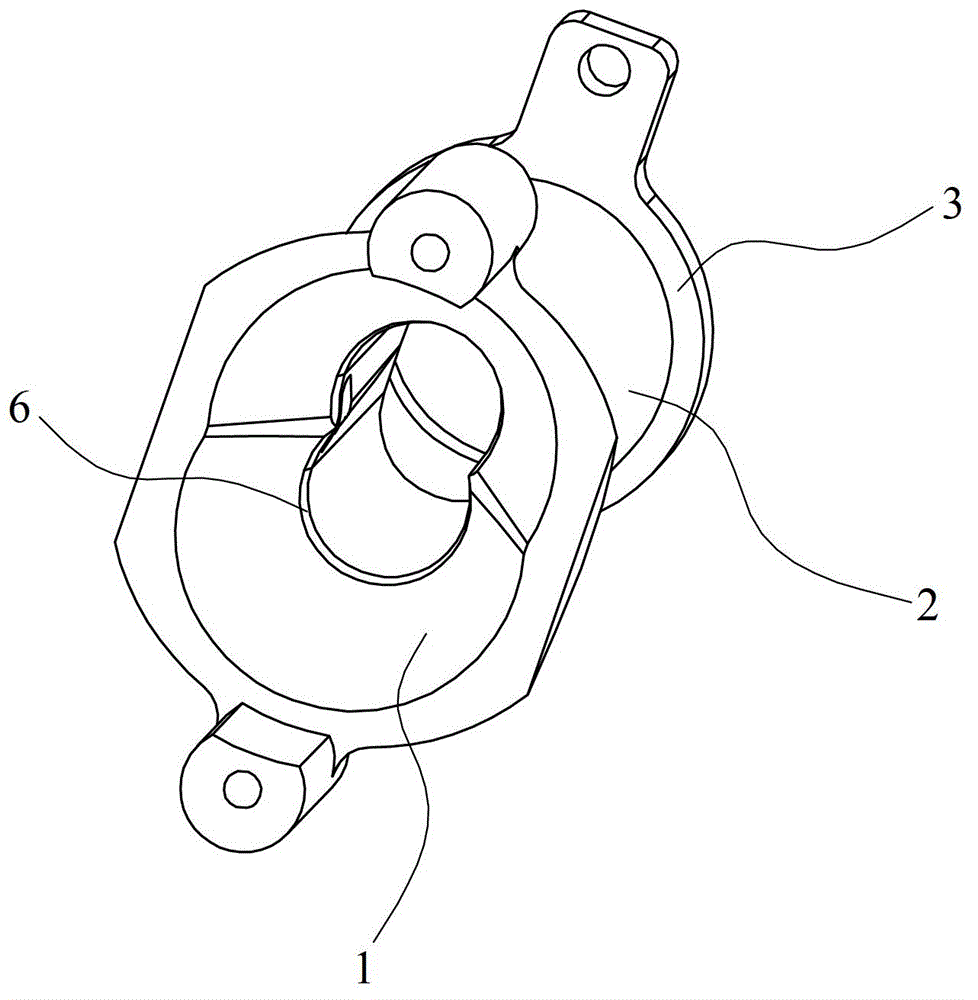
[0024] Such as Figure 1~6 As shown, the ejector tube in embodiment 1, its inner cavity is along the direction from the inlet to the outlet, followed by the horn section 1, the transition section 2 and the tail interface 3 that is compatible with the burner burner 8, and the horn section 1 and the A mouth 6 is formed between the transition sections 2, wherein a hole 9 is radially penetrated in the pipe wall of the transition section 2 close to the mouth 6, and a bolt 5 is internally threaded in the hole 9, so that the bolt 5 can move up and down by turning the thread To change the cross-sectional area of ​​the transition section 2 where it is located, to block the ejection flow, thereby changing the ejection coefficient.

[0025] The outer contour of the cross section of the horn section 1 (that is, the cross section of the cavity surrounded by the horn section) is formed by the intersection of two circles, the centers of the two circles are located on the same first circle, a...

Embodiment 2

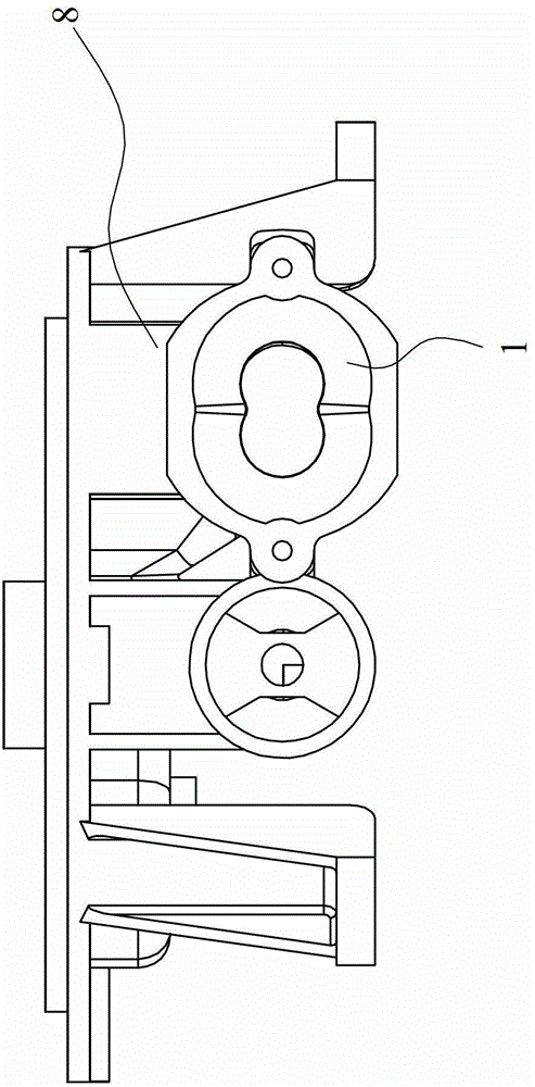
[0028] Such as Figure 7 As shown, the difference between the ejector tube in embodiment 2 and embodiment 1 is that the outer contour of the horn section 1 is formed by the intersection of three circles, the centers of the three circles are located on the same first circle, and relative to the The center of the first circle is evenly distributed, the radius r of the circle is 5, the radius R of the first circle is 4, and the nozzles matched with the injection tube are set at the centers of the three circles, that is, the nozzles matched with the injection tube The number of nozzles is three. Compared with the single-nozzle injection pipe, the three-nozzle injection pipe can enhance the ejection ability of the injection pipe, and can inhale more air, which improves the primary efficiency of the burner with this injection pipe. air supply.

[0029] It can be seen from the above description that the cross-section of the horn section 1 is plum-shaped and gradually becomes smaller...


PUM


Abstract

The invention relates to an ejecting pipe. A horn section, a transition section and a tail interface which is matched with a combustor furnace head are sequentially arranged in an internal chamber of the ejecting pipe along the direction from an inlet to an outlet. A throat opening is formed between the horn section and the transition section; an outer contour of the horn section is formed by a plurality of circles or a plurality of ellipses in an intersecting mode; the ellipses are approximate to circles; centers of the circles or centers of the ellipses are arranged in a same first circle and are uniformly distributed relative to a center of the first circle; nozzles which are matched with the ejecting pipe are arranged on centers of the circles or centers of the ellipses; the number of the nozzles is equal to the number of the circles or the number of the ellipses; a cross section of the horn section is gradually decreased; a shape of a cross section of the throat opening is the same with that of the horn section; the cross section area of the transition section is gradually increased from a cross section area the same as that of the throat opening to a cross section area the same as that of the tail interface. The ejecting pipe has the advantages of avoiding mutual interferences among airflows at the beginning of ejection, adding primary air supplementary amount, promoting mutual mixing of the airflows entering into the internal chamber of the ejecting pipe and the air, improving primary air coefficient, increasing ejecting capability and accordingly improving energy efficiency of a combustor.

Description

technical field [0001] The invention relates to a burner of a gas cooker, in particular to an injection tube. Background technique [0002] Energy saving and environmental protection is the theme of today's society. With the implementation of energy efficiency ratings, many daily necessities are labeled with energy efficiency labels, but gas stoves, which are indispensable to the family and are frequently used, have not been implemented for a long time. The reason is that the open heating mode of the gas cooker determines that it is very difficult to improve its energy efficiency, especially the most widely used atmospheric gas cooker. To improve the energy efficiency of the atmospheric burner, from the existing methods, reducing the distance between the heated pot and the flame so that the flame is centered can effectively improve the combustion efficiency, but the above method will lead to insufficient secondary air and insufficient air supplement It will greatly increase...

Claims


Application Information

Patent Timeline
Patent Type & Authority Patents(China)
IPC IPC(8): F23D14/04
Inventor 刘晓刚王式兴郑军妹茅忠群诸永定徐德明
Owner NINGBO FOTILE KITCHEN WARE CO LTD
Why Eureka
Try Eureka