Supersonic air injection device

A supersonic, air technology, used in jet pumps, machines/engines, non-displacement pumps, etc., can solve problems such as affecting airflow mixing, airflow disturbance, and airflow that cannot be mixed well, to reduce the degree of mutual attraction, Improves mixing uniformity and reduces airflow disturbance issues

Active Publication Date: 2022-01-21
GUIZHOU YONGHONG AVIATION MACHINERY
View PDF3 Cites 2 Cited by
  • Summary
  • Abstract
  • Description
  • Claims
  • Application Information

AI Technical Summary

Problems solved by technology

Due to the limitation of installation space, the length of the air outlet section of the ejector on the aircraft is relatively short, resulting in poor mixing of the airflow; The walls of the flow channel are easily affected by the Bernoulli effect, which further affects the mixing of the airflow and ultimately affects the ejection effect
[0003] An existing patent for an air ejection device (CN110529438A, 2019-12-03) discloses the structure of an air ejection device, but the air ejection device requires a higher space occupation (that is, the ejection device is required to The size of the injection device is very small, and the requirements for the shape of the ejector device are not suitable. On the one hand, affected by the Bernoulli effect, the ejector device is still insufficient in the mixing uniformity of the ejected airflow and the ejected airflow. On the other hand, On the one hand, its unique C-shaped ejector tube structure and the distribution of the nozzles are prone to large airflow disturbances. The way the ejector tube is placed outside passively reduces the mixing area of ​​the ejected airflow and the ejected airflow, resulting in airflow Inhomogeneous mixing. In addition, due to the asymmetry of the ejector tube, serious airflow disturbance will occur when the ejector air velocity increases, and there is a weld between the ejector tube and the air duct shell, and the weld seam is irregular in shape. High processing requirements

Method used


Image

  • Supersonic air injection device
  • Supersonic air injection device
  • Supersonic air injection device

Examples


Embodiment Construction

[0040] The present invention will be further described below in conjunction with accompanying drawing and specific embodiment, but should not be interpreted as that the scope of the subject matter of the present invention is only limited to following embodiment, under the situation of not departing from above-mentioned technical thought of the present invention, all according to this field Various modifications, substitutions and alterations made by ordinary technical knowledge and common means are included in the scope of the present invention.

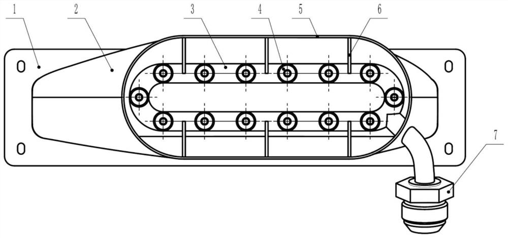
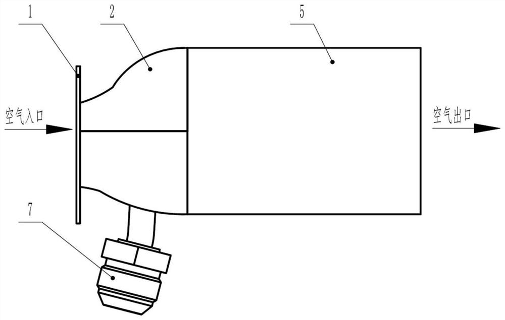
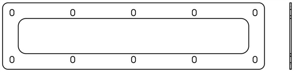
[0041] Such as Figure 1 to Figure 9 As shown, in this embodiment, the supersonic air injection device includes a mounting plate 1 , an air passage transition section 2 , an injection pipe 3 , a nozzle pipe 4 , a secondary cooling air passage 5 , a support plate 6 and an inlet nozzle 7 . All components of the ejection device are connected together by welding; image 3 , Figure 4 , Figure 7 The shown mounting plate 1, air duct tr...


PUM


Abstract

The invention discloses a supersonic air injection device. The supersonic air injection device is mainly composed of a mounting plate, an air duct transition section, an injection pipe, spray pipes, a secondary cooling air duct, a supporting plate and an inlet pipe nozzle. The injection pipe is arranged in the middle of the air duct transition section, and the spray pipes are symmetrically arranged Laval spray pipes. High-temperature and high-pressure gas enters through the inlet pipe nozzle, flows through the injection pipe and is sprayed out from the spray pipes, a negative pressure area is formed, and low-temperature air is sucked in from an air inlet, passes through the mounting plate and the air duct transition section, is mixed at the secondary cooling air duct and flows out from an air outlet. The supersonic air injection device is used for injecting the low-temperature air through the high-temperature and high-pressure gas, and the injected low-temperature air can serve as a cold source to be supplied to equipment for heat dissipation. The layout of the spray pipes and flow channels is more reasonable, the mixing uniformity of injection airflow and injected airflow is improved, and therefore the injection effect can be effectively improved.

Description

technical field [0001] The invention relates to a supersonic air injection device, which belongs to the field of ejector structure design. Background technique [0002] When the aircraft is on the ground, when it is necessary to suck in low-temperature ambient air as a cooling source to dissipate heat for the equipment, it is often necessary to use an ejector. Due to the limited installation space, the length of the air outlet section of the ejector on the aircraft is relatively short, resulting in poor mixing of the airflow; The walls of the flow channel are easily affected by the Bernoulli effect, which further affects the mixing of the airflow and finally affects the ejection effect. [0003] An existing patent for an air ejection device (CN110529438A, 2019-12-03) discloses the structure of an air ejection device, but the air ejection device requires a higher space occupation (that is, the ejection device is required to The size of the injection device is very small, an...

Claims


Application Information

Patent Timeline
Patent Type & Authority Applications(China)
IPC IPC(8): F04F5/16F04F5/44F04F5/46
CPCF04F5/16F04F5/44F04F5/466
Inventor 赵清王田卢继方陈官林陶刘远
Owner GUIZHOU YONGHONG AVIATION MACHINERY
Why Eureka
Try Eureka