Method and device for mechanically pressurizing, injecting and recovering waste steam for suction section

A waste steam and ejector technology, applied in mechanical equipment, jet pumps, machines/engines, etc., can solve the problem of low ejection coefficient, and achieve the effect of high energy recovery rate, simple equipment and good economy

Inactive Publication Date: 2012-10-03
TIANJIN UNIV
View PDF8 Cites 2 Cited by
  • Summary
  • Abstract
  • Description
  • Claims
  • Application Information

AI Technical Summary

Problems solved by technology

However, the suction of waste steam by the ejector in practical applications is realized by the negative pressure difference formed between the negative pressure formed by the high-speed injection of the working fluid and the pressure of the waste steam source, so the ejection coefficient is relatively low

Method used


Image

  • Method and device for mechanically pressurizing, injecting and recovering waste steam for suction section
  • Method and device for mechanically pressurizing, injecting and recovering waste steam for suction section
  • Method and device for mechanically pressurizing, injecting and recovering waste steam for suction section

Examples


Embodiment 1

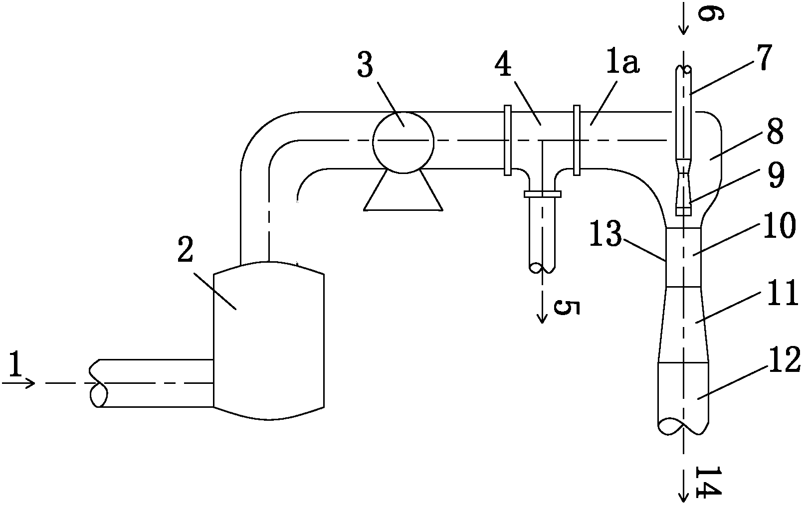
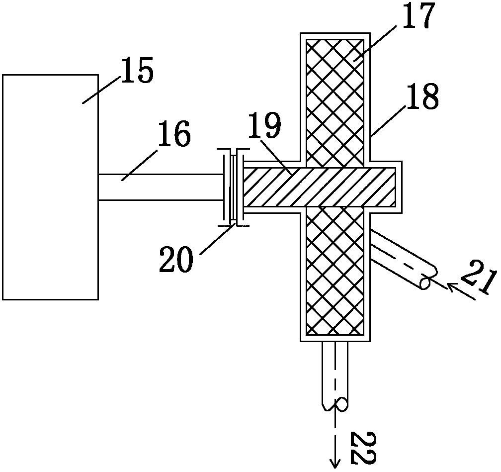
[0027] Mechanically pressurized steam ejectors are used to recover waste steam, such as figure 1 shown. The waste steam 1 from the production process enters the heating device 2 for heating to form supersaturated waste steam, and then enters the pressurizer 3 to be pressurized and then sent to the vapor-liquid separator 4 to discharge the possible condensed water 5 and send the pressurized steam into the Ejector 13. Wherein pressurizing machine 3 structures such as figure 2 As shown, the pressing machine casing 18 isolates the pressing machine rotating shaft 19 from the outside, so that the pressing machine rotating shaft 19 and the rotating shaft 16 of the motor 15 form two independent shafts respectively, and the motor and the pressing machine are arranged therebetween. Magnetically conductive connection 20 of the rotating shaft. The rotational power of the rotating shaft of the motor at the connecting piece is transmitted to the rotating shaft of the pressing machine th...

Embodiment 2

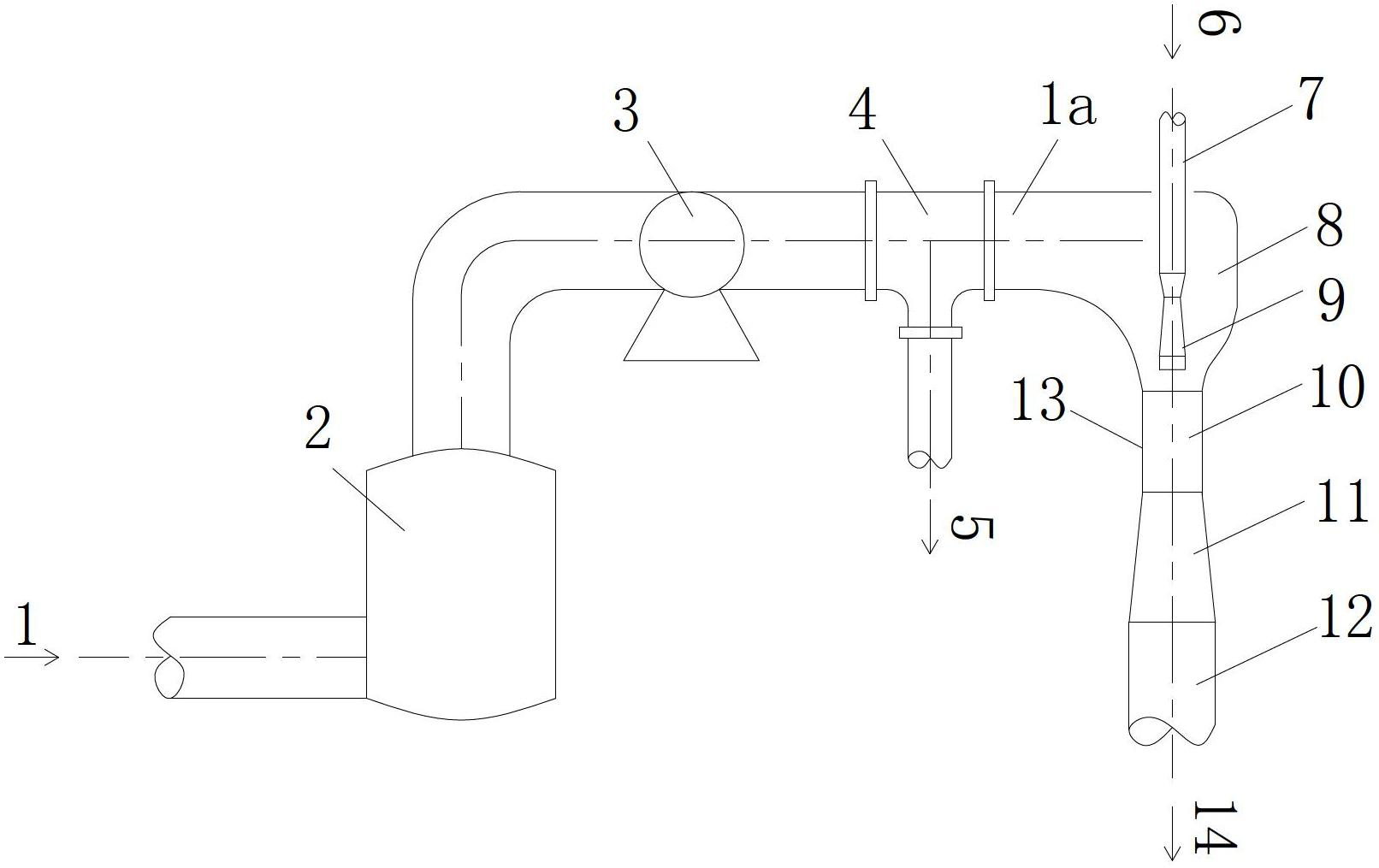
[0029] The device for recovering waste steam by mechanically pressurized water ejector such as figure 1shown. The waste steam 1 from the production process enters the heating device 2 for heating to form supersaturated waste steam, enters the pressurizer 3 and is pressurized, and is directly sent to the ejector 13 without passing through the vapor-liquid separator. The pressurized water 6 is sent into the nozzle 9 by the working water inlet 7 . When the nozzle outlet reaches a very high speed, most of the pressure potential energy is converted into kinetic energy, so that the pressure of the pressurized water is reduced below the pressure of the pressurized ejection steam, forming a local relative negative pressure, and the pressurized waste steam is ejected to the Reception room 8. Further enter the mixing chamber 10 to fully mix and balance the speed and energy. At the outlet section of the mixing chamber 10, a uniform velocity field and energy field are established to for...

Embodiment 3

[0031] The application example of using steam as the working fluid to eject the waste steam mechanically pressurized ejector is the same as that of Example 1, the difference is that no vapor-liquid separator is installed after the pressurizer, and the waste steam is heated to the heating device 2 It is realized by adding a small amount of working steam to the inlet.


PUM


Abstract

The invention relates to a method and a device for mechanically pressurizing, injecting and recovering waste steam for a suction section. The waste steam is injected and aspirated by utilizing working steam; a pressurizing machine is arranged on a waste steam pipeline; and the waste steam is sent into an injector after being pressurized. Water is utilized as a working fluid; after being pressurized by using a water pump, the water is sent into the injector and is used for aspirating the waste steam; the pressurizing machine is arranged on the waste steam pipeline; and the waste steam is sent into the injector after being pressurized by the pressuring machine. By using the method and the device, the pressure of the waste steam is improved by utilizing mechanical pressurization; the injection propelling force is increased; the injection effect is obviously improved; and the recovery and utilization rate of the energy of the waste steam is improved drastically. By using the method and the device, not only are the problems of the energy loss and the atmospheric environmental pollution caused by the waste of the waste steam of an ordinary evaporation operation unit solved, but also the method and the device, compared with a conventional steam saving technique, have the characteristics that equipment is simple, the recovery rate of the energy is high, and the economical efficiency is good.

Description

technical field [0001] The invention relates to a method and device for using high-pressure steam or pressurized water as a working fluid to inject and recover waste steam for reuse, belonging to the field of energy recovery and environmental protection, and in particular to a method for recovering waste steam by mechanically pressurizing and injecting in the suction section and devices. Background technique [0002] In the industrial production process, the evaporation process is a widely used operating unit. This process consumes a lot of energy, has low thermal efficiency, and produces a large amount of waste steam. This part of waste steam contains a lot of heat energy, and direct release will cause energy waste and air pollution. If it can be recycled, energy saving and emission reduction can be achieved at the same time. [0003] In large-scale evaporation systems, multi-effect evaporation and heat pump evaporation technologies are often used to reduce steam consumpt...

Claims


Application Information

Patent Timeline
Patent Type & Authority Applications(China)
IPC IPC(8): F04F5/04F04F5/16
Inventor 张书廷凌莹王润娟张蕊陈健敏
Owner TIANJIN UNIV
Why Eureka
Try Eureka