Threading guide device for double-end crimping

A technology of guiding device and crimping device, which is applied in the direction of connection, line/collector parts, electrical components, etc., which can solve the problems that the crimping surface of the terminal cannot be guaranteed, affects the appearance, and is labor-intensive, etc., and achieves automatic feeding Action, solve the interference of the position, improve the effect of work efficiency

Inactive Publication Date: 2013-08-07
BEIJING UNIV OF TECH
View PDF5 Cites 17 Cited by
  • Summary
  • Abstract
  • Description
  • Claims
  • Application Information

AI Technical Summary

Problems solved by technology

The conductor connection here, that is, the connection between the miniseal crimping tube and the wire needs to be completed by the crimping force generated by the crimping device. At present, manual crimping pliers are widely used for double-ended crimping. The operation process is cumbersome. First, insert the wire into the miniseal One side hole of the butt joint, and crimp with manual crimping pliers, then reverse the crimping direction, insert the wire into the other side of the miniseal butt joint, and then crimp with manual crimping pliers
Manual crimping is heavy work, labor-intensive, slow, and inefficient. Also, because the two ends of the terminal are crimped separately, the crimping surfaces on both sides of the terminal cannot be guaranteed to be consistent, which affects the appearance. It can be seen that it is necessary to realize double-ended crimping automation. In order to facilitate simultaneous threading of both ends, the present invention provides a threading guide device for double-end crimping. The present invention is simple in structure, low in cost, and can be conveniently threaded to both ends of the butt terminal at the same time, greatly improving the efficiency of double-end crimping. efficiency

Method used


Image

  • Threading guide device for double-end crimping
  • Threading guide device for double-end crimping
  • Threading guide device for double-end crimping

Examples


Embodiment Construction

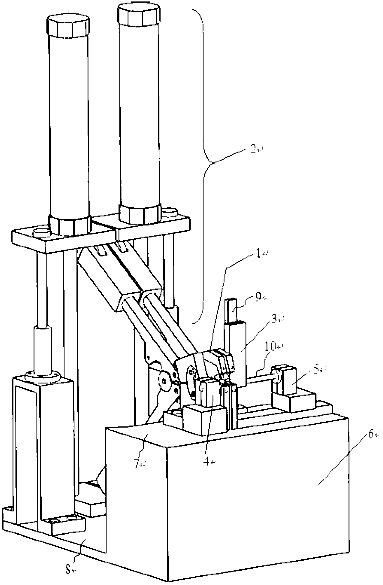
[0015] The process of double-ended terminal crimping is simply to put the two ends of the double-ended terminal through the wires for crimping. The present invention relates to a double-end crimping device, such as figure 1 As shown, the pliers assembly 1 adopts a left-right symmetrical layout to realize simultaneous crimping at both ends, the clamp arm assembly 2 and the drive assembly 3 cooperate to realize automatic crimping, and the terminal box assembly 3 is cleverly designed to automatically feed materials; and in order to realize the automatic crimping process Both ends can be threaded at the same time, and the present invention provides a threading guide device, which includes two sets of threading guide assemblies.

[0016] The implementation process in which the device of the present invention is applied to double-end crimping is described in detail below:

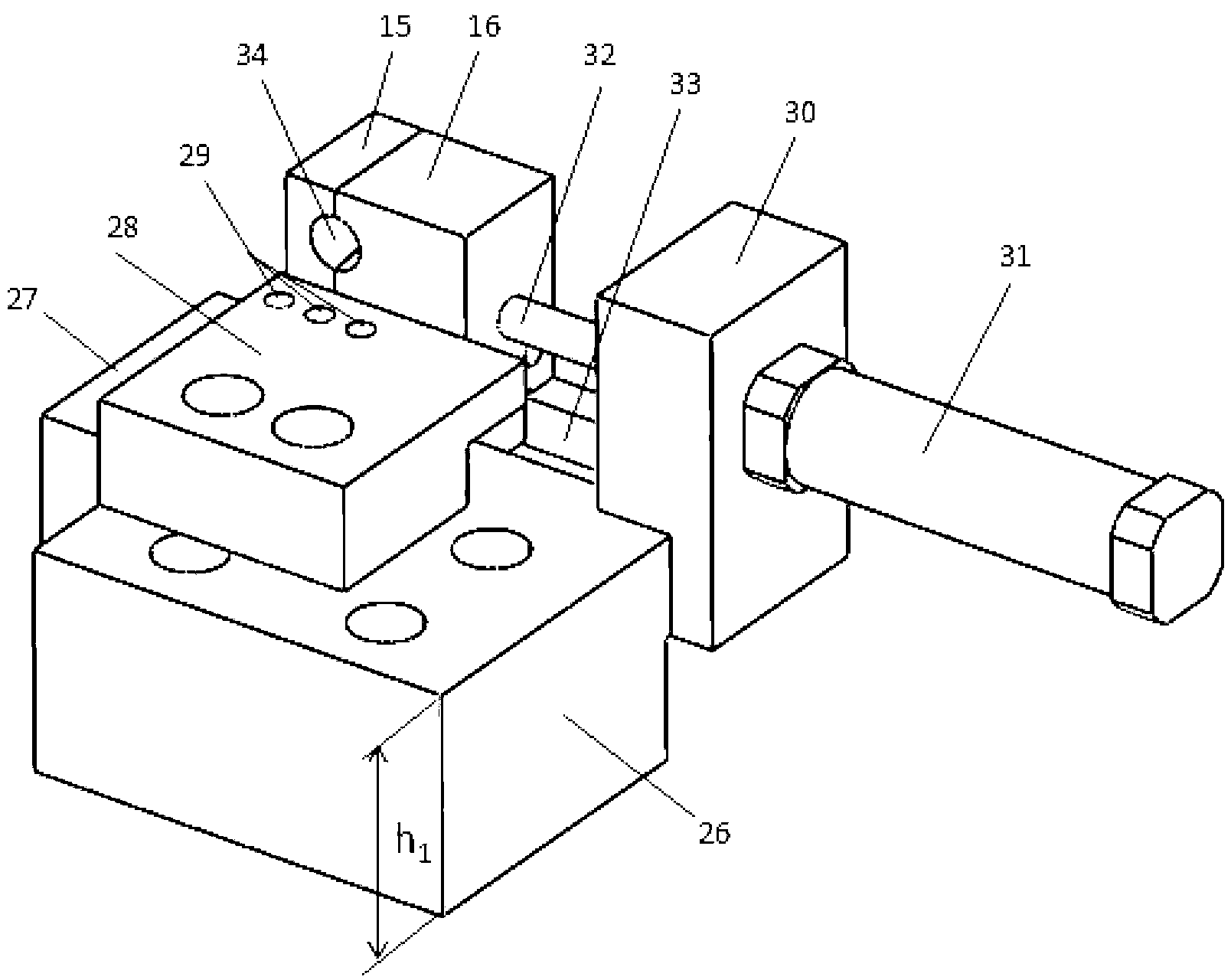
[0017] Such as image 3 As shown, a threading hole block adjustment plate 27 is fixed behind the threading ...


PUM


Abstract

The invention relates to a threading guide device for double-end crimping and belongs to the field of appliance tools. A terminal crimping device is used for crimping incoming leads of two ends of a butt joint terminal so as to enable two ends of the terminal and the leads to be electrically and mechanically inseparably connected. The threading guide device is characterized by comprising threading guide components for double-end crimping. A rear threading hole block in each threading guide component is fixed, and a front hole block moves backwards along a guide groove and forms a conical threading hole with the rear hole block in a closed manner. When the conical threading hole and the axis of a pressing pliers jaw are superposed, simultaneous threading of two ends of the butt joint terminal on the pressing pliers jaw is benefited. The front hole block moves forwards along the guide groove, the conical hole is opened, and the terminal after being crimped can be taken out conveniently. The threading guide device is simple in structure and low in cost, threading of two ends at the same time is greatly facilitated, and operating efficiency is improved.

Description

technical field [0001] The invention belongs to the field of electrical tools, and relates to an automatic crimping device for a butt joint terminal that crimps a conductive wire and a coaxial butt terminal. The crimping device generates a crimping force. The ground and the mechanical ground are inseparably connected. It can replace the manual crimping pliers widely used at present, and has the advantages of high operating efficiency, firm crimping, and good appearance quality. Background technique [0002] MiniSeal coaxial butt joint terminal is a tinned copper alloy shielded wire joint, which is used in conjunction with a transparent heat-shrinkable sleeve, and is widely used in the connection of shielded cables including coaxial cables and multi-core cables. The conductor connection here, that is, the connection between the miniseal crimping tube and the wire needs to be completed by the crimping force generated by the crimping device. At present, manual crimping pliers ...

Claims


Application Information

Patent Timeline
Patent Type & Authority Applications(China)
IPC IPC(8): H01R43/052H01R43/055
Inventor 王新华高燕龚志奔涂承媛孙树文郑刚
Owner BEIJING UNIV OF TECH
Why Eureka
Try Eureka