Three-level inverter dead time compensation control method

A three-level inverter and dead zone compensation technology, which is applied to electrical components, AC power input to DC power output, output power conversion devices, etc. Problems such as pressure drop

Inactive Publication Date: 2013-08-07
NORTH CHINA UNIVERSITY OF TECHNOLOGY
View PDF1 Cites 35 Cited by
  • Summary
  • Abstract
  • Description
  • Claims
  • Application Information

AI Technical Summary

Problems solved by technology

[0003] The technology of the present invention solves the problem: it overcomes the defect that the power device turn-on and turn-off delay and tube voltage drop are not considered in the existing inverter dead zone compensation method, and proposes a novel and simple three-level inverter dead zone compensation method. Zone compensation control method improves system performance

Method used


Image

  • Three-level inverter dead time compensation control method
  • Three-level inverter dead time compensation control method
  • Three-level inverter dead time compensation control method

Examples


Embodiment Construction

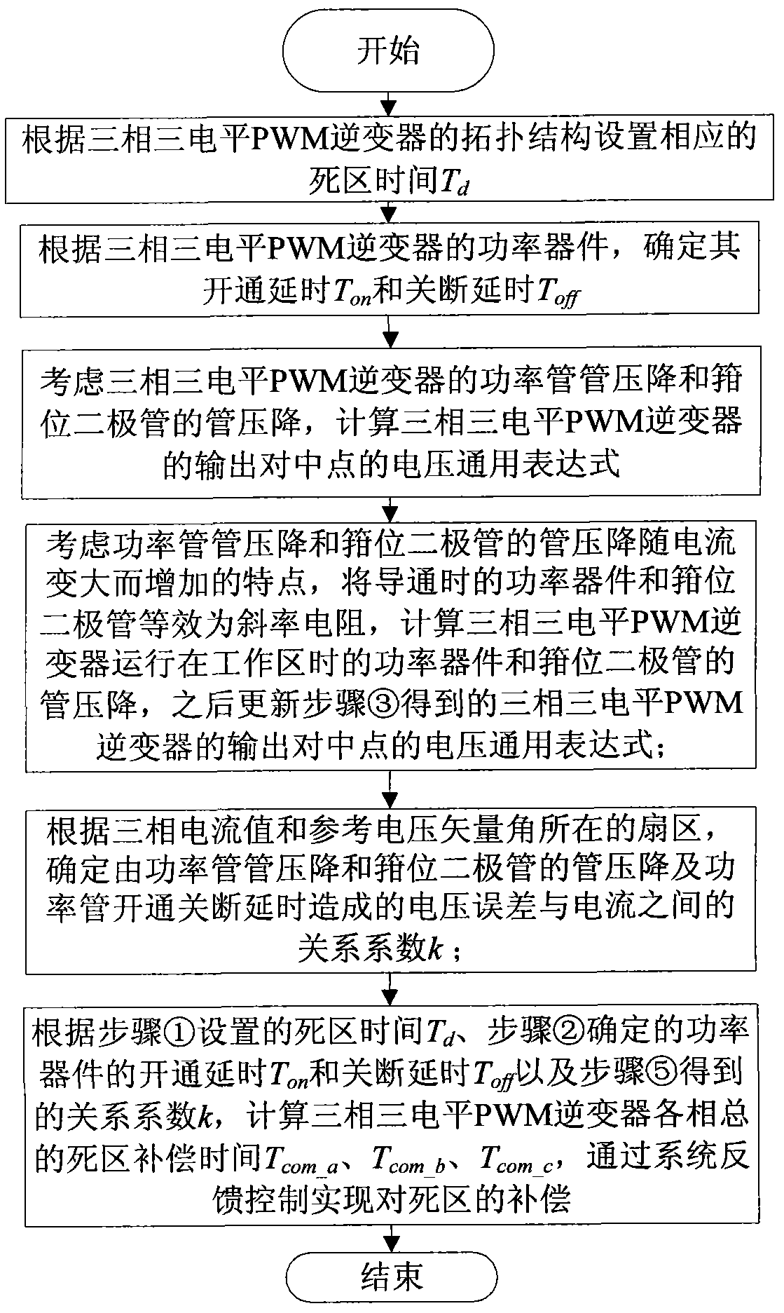
[0113] A dead zone compensation control method for a three-level inverter, such as figure 1 As shown, the specific steps are:

[0114] ① According to the topology structure of the three-phase three-level PWM inverter, considering the delay time for the switch device to be completely turned off, this embodiment sets the corresponding dead time T d = 10μs;

[0115] ② According to the power device of the three-phase three-level PWM inverter, determine its turn-on delay T on = 7μs and turn-off delay T off = 7μs;

[0116] ③Considering the power tube voltage drop of the three-phase three-level PWM inverter and the tube voltage drop of the clamping diode, calculate the general expression of the output midpoint voltage of the three-phase three-level PWM inverter;

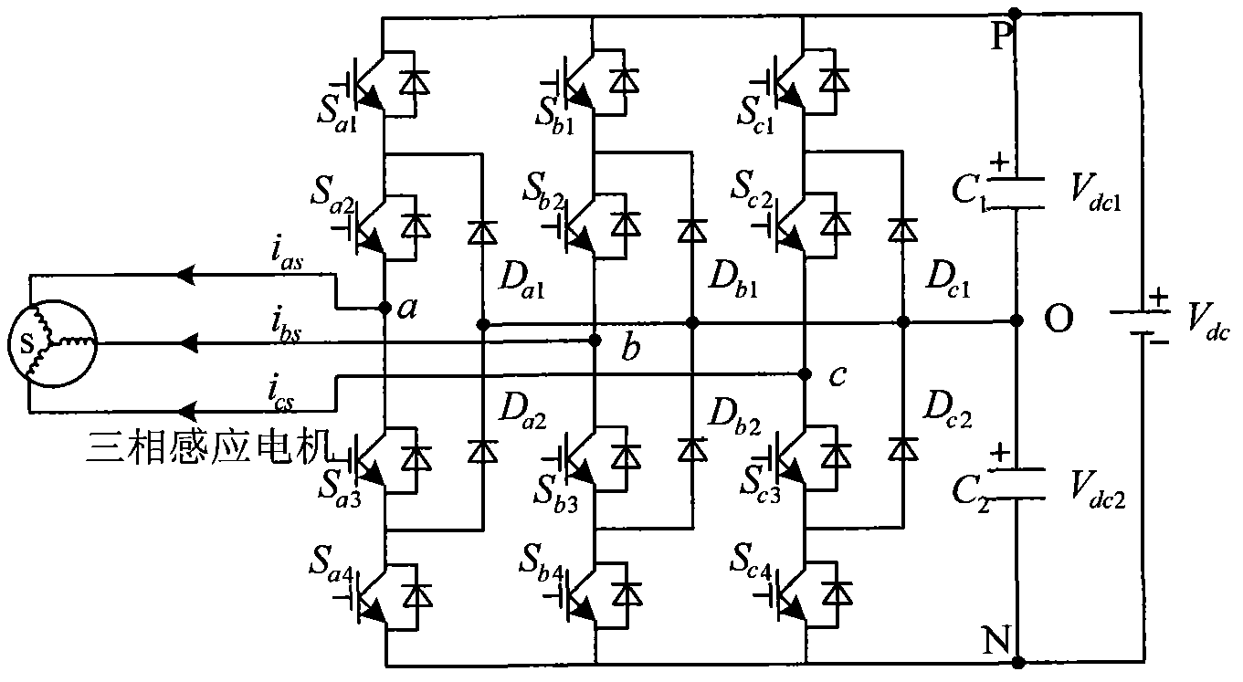
[0117] Such as figure 2 As shown, taking phase A as an example, when i as When >0, the voltage of the actual output point a to the midpoint O is

[0118] V ao = ...


PUM


Abstract

A three-level inverter dead time compensation control method is used for compensating the decrease of system performance caused by dead time. According to the topological structure of a three-phase three-level PWM (pulse width modulation) inverter, the method first sets corresponding dead time and determines the on-off delays of power elements in the inverter; the method then considers the tube voltage drops of the power transistors of the inverter and the tube voltage drops of clamping diodes of the inverter and calculates the common voltage expression of the output neutral point of the inverter; afterwards, according to the sector with three-phase current value and a reference voltage vector, the method determines the relational coefficient between voltage error caused by the tube voltage drops of the power transistors, the tube voltage drops of the clamping diodes and the on-off delays of the power transistors and current, and thereby the total dead time compensation time of each phase of the three-level PWM inverter is worked out. The method takes the dead time, the on-off delays of the power elements and the tube voltage drops into full consideration, solves the problem of voltage and current distortion caused by the dead time effect in the three-level inverter, and enhances system performance.

Description

technical field [0001] The invention relates to a dead-zone compensation control method for a three-level inverter, which is used for compensating the decrease of system performance caused by the dead zone, and is especially suitable for the field of frequency conversion and speed regulation of high-voltage and high-power AC motors. Background technique [0002] The three-level topology has the advantages of large output capacity, high output voltage, and low current harmonic content, which makes the three-level structure widely used in the field of frequency conversion and speed regulation of high-voltage and high-power AC motors. In order to prevent the bridge arm of the inverter from passing through, a dead zone must be added to the complementary trigger signal of the same bridge arm to ensure that the complementary switching tube can be turned on only after the switching tube on the same bridge arm is reliably turned off. However, due to the introduction of dead time, th...

Claims


Application Information

Patent Timeline
Patent Type & Authority Applications(China)
IPC IPC(8): H02M7/487H02M7/5387
Inventor 周京华李正熙章小卫陈亚爱贾斌潘逸菎祝天岳
Owner NORTH CHINA UNIVERSITY OF TECHNOLOGY
Why Eureka
Try Eureka