Eureka AIR delivers breakthrough ideas for toughest innovation challenges, trusted by R&D personnel around the world.

Environmental energy conversion device

An energy conversion and environmental technology, applied in electrical components, generators/motors, etc., to solve problems such as disorder, consumption of mechanical energy, hazards, etc.

Inactive Publication Date: 2013-08-07
NANJING UNIV OF AERONAUTICS & ASTRONAUTICS
View PDF2 Cites 7 Cited by
  • Summary
  • Abstract
  • Description
  • Claims
  • Application Information

AI Technical Summary

Problems solved by technology

However, lithium batteries and supercapacitors need to be charged before they can be used, and in order to increase energy density, large volume and weight are required
Solar cells need light to be used. Fuel cells consume fuel and cause great harm to the environment. Zinc oxide nanogenerators produce discontinuous electrical output, and capacitors are needed to store the generated electricity, which also consumes Mechanical energy
However, there is another form of energy, the energy of thermal motion of molecules, atoms, ions, and particles. For example, the thermal motion speed of gas molecules is as high as 1000 m / s, and the energy of thermal motion of ions in aqueous solution at room temperature is as high as 300 m / s. Because this motion is chaotic, although in the field of scientific research, there is no report of converting the energy of thermal motion into electrical energy, but the energy of this thermal motion is converted into electrical energy in nature, but it happens all the time, such as lightning

Method used


Image

  • Environmental energy conversion device
  • Environmental energy conversion device
  • Environmental energy conversion device

Examples


Embodiment 1

[0052] Embodiment 1, platinum-gold-purified water test

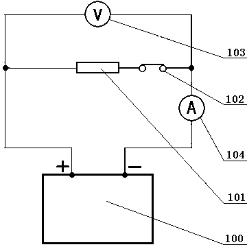
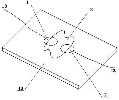
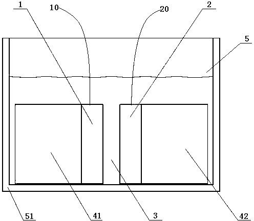
[0053] Wherein, the anode body 1 is made of platinum, the anode body 2 is made of gold, and the droplet as the intermediary body is made of pure water. At an ambient temperature of 25°C, the open circuit voltage obtained by the test is 205 mV, and the current obtained after loading a 400 kΩ load is 0.21 μA, and the calculated internal resistance is 565 kΩ.

Embodiment 2

[0054] Embodiment 2, platinum-gold-sodium chloride aqueous solution test

[0055] Replace the above pure water with an aqueous solution of NaCl with a concentration of 1 mole per liter. At an ambient temperature of 25°C, the open circuit voltage obtained by the test is 0.21 V, and the current obtained after loading a 400 kΩ load is 0.34 μA, and its internal resistance is calculated. is 220 kΩ.

[0056] The design of the structure is mainly to facilitate the integration of this energy conversion device, making the patent of the present invention oriented to industrial production. It is well known to those skilled in the art that other film-body, film-film, body-body system power generation devices in electrolyte solution other than the above-mentioned Examples 1 and 2 are within the protection scope of this patent.

[0057] 2. Film-film test

[0058] 1. Film-film test structure

[0059] An environmental energy conversion device includes an energy conversion unit. energy con...

Embodiment 3

[0062] Embodiment 3, the test of long-time current output

[0063] CuCl as intermediary 3 2 The concentration of the aqueous solution is 5 moles per liter, the temperature of the solution is 25°C, and the open circuit voltage is 0.5 V according to the test. In the case of loading a 400 kΩ load between the positive and negative electrodes, the relationship between the output current and time of the environmental energy conversion device within 100 hours of testing is as follows Figure 4 shown. Depend on Figure 4As shown, in this embodiment, after 48 hours, the current output is basically stable at about 1.14 microamperes, and the calculated internal resistance is about 40 kΩ.


PUM


Abstract

The invention discloses an environmental energy conversion device which comprises an energy conversion unit. The energy conversion unit comprises an anode body, a cathode body and a intermediate body; the anode body is not connected with the cathode body; the intermediate body is positioned between the anode body and the cathode body and is respectively in contact with the anode body and the cathode body; the anode body and the cathode body are electric conductors; the anode body and the cathode body are asymmetric; and chemical reaction is not performed between the intermediate body and the anode body as well as the cathode body. The environmental energy conversion device utilizes a surface effect to spontaneously convert environmental heat energy into electric energy, provides a revolutionary energy acquisition manner and has groundbreaking significance; and the environmental energy conversion device is widely applied, can be used as a power supply and a refrigerating device and also can be used as a temperature sensing device, or a solution ion concentration detection device or a gas and liquid flow rate detection device.

Description

technical field [0001] The invention relates to environmental heat energy conversion equipment of a new principle. Background technique [0002] Energy conversion and storage technologies include conversion of solar, thermal, vibrational, chemical and wind energy into electricity. Among these numerous energy conversion technologies, lithium batteries, supercapacitors, solar cells, fuel cells, and ZnO nanogenerators have received the most attention. However, lithium batteries and supercapacitors need to be charged before they can be used, and in order to increase energy density, large volume and weight are required. Solar cells need light to be used. Fuel cells consume fuel and cause great harm to the environment. Zinc oxide nanogenerators produce discontinuous electrical output, and capacitors are needed to store the generated electricity, which also consumes Mechanical energy. However, there is another form of energy, the energy of thermal motion of molecules, atoms, ion...

Claims


Application Information

Patent Timeline
Patent Type & Authority Applications(China)
IPC IPC(8): H02N11/00
Inventor 台国安刘劲松
Owner NANJING UNIV OF AERONAUTICS & ASTRONAUTICS
Why Eureka
Eureka Blog
Learn More