Gathering type solid-liquid separation machine

A technology of solid-liquid separator and frame, which is applied in the direction of filtration separation, separation method, fixed filter element filter, etc., which can solve the problems of small water passing area, high power and weak strength of the grid cleaning machine, and achieve increased Water flow, reduce equipment cost and operating energy consumption, good rigidity

Active Publication Date: 2013-08-14
JIANGSU ZHAOSHENG ENVIRONMENTAL PROTECTION TECH CO LTD
View PDF6 Cites 4 Cited by
  • Summary
  • Abstract
  • Description
  • Claims
  • Application Information

AI Technical Summary

Problems solved by technology

[0003] In view of the shortcomings of the above-mentioned existing grid cleaning machine, such as high power, weak strength, and small water passing area, the applicant provides a solid-liquid separator with a reasonable structure, so that it can meet a large amount of water passing, and at the same time, it has various forms. , can be flexibly adapted to a variety of applications

Method used


Image

  • Gathering type solid-liquid separation machine
  • Gathering type solid-liquid separation machine
  • Gathering type solid-liquid separation machine

Examples


Embodiment 1

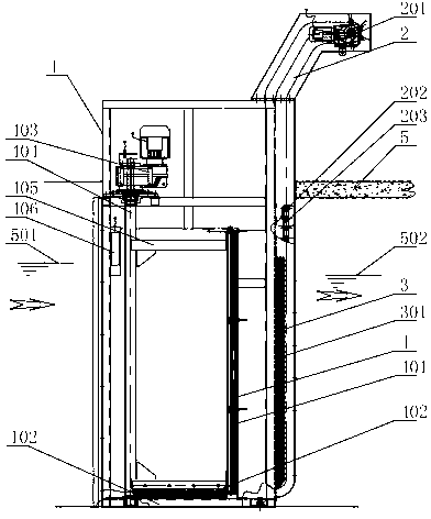
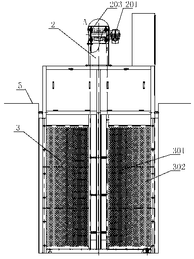
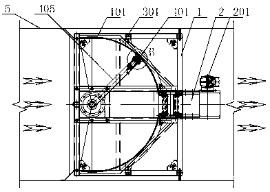
[0034] Such as Figure 1 to Figure 3 As shown, the filter device 3 is composed of two arc filter plates 301 of nearly 1 / 4 circular arc surface, and the filter plate fixing side frame 101 of the frame 1 is vertically fixed on the cross section of the water channel 5, and its concave The inlet face faces the water inlet side; the surface of the curved filter plate 301 is densely covered with filter holes 302, and the diameter of the filter holes 302 is determined according to the water flow and impurities. In this embodiment, the diameter of the filter holes is 2mm. The slag extracting device 2 is arranged between the two arc-shaped filter plates 301, located in the center of the cross-section of the water channel 5, and the width accounts for about 20% to 30% of the cross-section of the water; the structure of the slag extracting device 2 in this embodiment is similar to Existing rotary grid cleaning machines, such as Figure 4 The slag extraction and dehydration grid assembly...

Embodiment 2

[0041] Such as Image 6 , Figure 7 As shown, the filter hole slag cleaning device 4 of the present embodiment is a vacuum suction structure, and other components are the same as those of the first embodiment. The vacuum pump 411 and the vacuum storage tank 412 are arranged on the top of the frame 1, and the position of the roller brush hole cleaner 401 is set in the first embodiment. The slag rotating main shaft 404 and the pipeline inside the slag cleaning rotating arm 405 are connected with the vacuum pump 411 and the vacuum storage tank 412, and an electric ball valve 413 is provided to realize the opening and closing of the pipeline, and the slag cleaning rotating main shaft 404 is realized through the rotating seal 414 when it rotates connected to the vacuum system. Such as Figure 7 As shown, the opening of the vacuum suction nozzle 415 faces the curved filter plate 301 , and forms a relatively airtight space under the closure of the plastic scraping strips 408 on bo...

Embodiment 3

[0043] Such as Figure 8 As shown, the slag extraction device 2 of this embodiment is a screw slag extraction structure, and other components are the same as those of the first embodiment. The slag extraction motor 201 drives the rotation of the bidirectional or unidirectional screw screw 206, and the slag extraction scraper 205 fitted on the screw screw 206 by the screw nut moves up and down to filter the lower part of the water body filter device 3 and collect the grid slag at the end Elevate to the upper part, and scrape and remove it into the slag hopper on the upper part of the water channel 5 by the slag unloading scraper 204 swinging on the top for processing.


PUM


Abstract

The invention discloses a gathering type solid-liquid separation machine which is fixed in a water channel by a rack. The machine is composed of a filtering device, a residue lifting device and a filtration hole residue cleaning device, wherein the filtering device is a fixed filter plate structure, the width of the filtering device at least accounts for about 50% of the section of passing water, the residue lifting device is arranged on the tail end of the filtering device, the filtration hole residue cleaning device is arranged on the filtering device in a reciprocating manner and used for cleaning filtration holes of a filter plate. The filtering device disclosed by the invention is a fixed filter plate structure, so that the vast majority of flow filtering function is finished by the filter plate, and the filter plate has strong filter capacity, good reliability and is difficult to damage; and according to the gathering type solid-liquid separation machine, barrier residues are naturally gathered in the tail end of a concave arc by utilizing a scouring effect of flow, then the barrier residues are lifted by the residue lifting device which is arranged on the tail end of the concave arc, the width of the residue lifting device only accounts for 20-30% of the section of the passing water of the whole water channel, the scouring force of the flow is greatly reduced, and the gyration running resistance is reduced, thereby greatly reducing the equipment cost and the running energy consumption.

Description

technical field [0001] The invention relates to the field of environmental protection equipment for sewage treatment, in particular to a double-type solid-liquid separator. Background technique [0002] At the water intakes of sewage treatment plants, drinking water intakes, large-scale hydropower stations, comprehensive treatment projects for rivers and lakes, rainwater drainage and sewage lifting pumping stations, etc., equipment such as rotary grid cleaning machines are often used to remove floating objects and sediments from water intakes. The waste is salvaged and removed, and the dirt is squeezed dry, dehydrated, compressed and discharged. However, in the existing grid cleaning machine, the fixed grid bars of the water-passing grid are arranged in the middle of the rotary crawler, which must determine that there is a certain distance between the grid and the river bottom, resulting in a reduction in the water-passing area, especially for channels with low water levels....

Claims


Application Information

Patent Timeline
Patent Type & Authority Applications(China)
IPC IPC(8): B01D29/64B01D29/94B01D29/01
Inventor 荣杰尹志强周震球
Owner JIANGSU ZHAOSHENG ENVIRONMENTAL PROTECTION TECH CO LTD
Why Eureka
Try Eureka