Pipeline configuration structure of triple-inlet air cooler system for hydrogenation reaction effluents

A technology of hydrogenation reaction and air cooler, applied in the direction of heat exchanger type, heat exchanger shell, indirect heat exchanger, etc., can solve problems such as ineffective effect, tube bundle leakage, high cost, etc., to avoid eddy current phenomenon, increase Uniformity, reducing the effect of multiphase flow erosion corrosion

Active Publication Date: 2013-08-14
ZHEJIANG SCI-TECH UNIV
View PDF3 Cites 8 Cited by
  • Summary
  • Abstract
  • Description
  • Claims
  • Application Information

AI Technical Summary

Problems solved by technology

The research results after upgrading the material show that although the flow corrosion resistance of the air cooler tube bundle can be improved by upgrading the material, it is expensive and has no obvious effect on the operation of the entire hydrogenation air cooler system. Leakage and explosion accidents of tube bundles still occur after material upgrade

Method used


Image

  • Pipeline configuration structure of triple-inlet air cooler system for hydrogenation reaction effluents
  • Pipeline configuration structure of triple-inlet air cooler system for hydrogenation reaction effluents

Examples


Embodiment Construction

[0016] The present invention will be further described below in conjunction with drawings and embodiments.

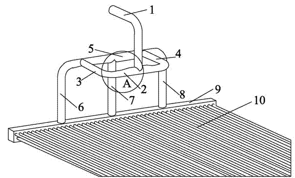
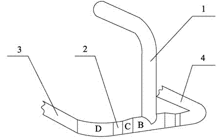
[0017] Such as figure 1 As shown, it is a structural schematic diagram of the present invention, including an inlet main pipe 1, a first pipeline 2, a second pipeline 3, a third pipeline 4, a fourth pipeline 5, a fifth pipeline 6, a sixth pipeline 7, a seventh pipeline 8, Air cooler tube box 9, air cooler tube bundle 10. Among them, the inlet end of the inlet main pipe 1 is in the horizontal direction, and the outlet end is in the vertical downward direction. The horizontal section of the inlet main pipe 1 is connected with the vertical section through a pipe fitting (90° elbow). The different-diameter pipes at both ends are connected to the midpoint of the first pipeline 2, and the two ends of the first pipeline 2 are respectively connected to the second pipeline 3 and the third pipeline 4 through pipe fittings (90° elbow), and the inlet main pipe 1 is vertical The d...


PUM


Abstract

The invention discloses a pipeline configuration structure of a triple-inlet air cooler system for hydrogenation reaction effluents. The pipeline configuration structure is characterized in that an inlet header pipe is perpendicularly downwardly communicated with a middle point of a first pipeline, two ends of the inlet header pipe are respectively communicated with a second pipeline and a third pipeline, and a plane formed by the second pipeline and the third pipeline is perpendicular to a plane formed by the inlet header pipe and the first pipeline; the tail end of the second pipeline and the tail end of the third pipeline are perpendicularly communicated with a fourth pipeline, two ends and the center point of the fourth pipeline are respectively perpendicularly communicated with a fifth pipeline, a seventh pipeline and a sixth pipeline, a plane formed by the fifth pipeline, the seventh pipeline and the sixth pipeline is perpendicular to a plane formed by the first pipeline, the second pipeline and the third pipeline, and the fourth pipeline is quartered by three joints along the length direction of the fourth pipeline and the three joints are formed by the fourth pipeline jointed with the second pipeline, the third pipeline and the sixth pipeline respectively and the tail end of the fifth pipeline, the tail end of the sixth pipeline and the tail lend of the seventh pipeline are perpendicularly communicated with an air cooler header and quarter the air cooler header. The pipeline configuration structure has the advantages that phenomena of multi-phase flow erosion corrosion, deposition and blockage of ammonium salt and under-deposit corrosion due to uneven distribution of flow parameters of existing air cooler tube bundles can be reduced, unintended shutdown accidents are reduced, and the safe operation cycle of the air cooler system for the hydrogenation reaction effluents is prolonged.

Description

technical field [0001] The invention relates to an air cooler system, in particular to a piping structure of a three-inlet hydrogenation reaction effluent air cooler system. Background technique [0002] The petrochemical industry is a pillar industry in my country. Hydrocracking is an important refining process in refineries, and the air cooler system for hydrogenation reaction effluent is one of the key equipment in hydrocracking units. In recent years, with the aggravation of the world's energy crisis, major oil refineries have been developing towards the direction of inferior crude oil, large-scale equipment, and harsh working conditions, which has caused the general flow corrosion failure of the hydrogenation reaction effluent air cooler system , frequent tube bundle blockage, perforation, tube explosion, etc. have caused many unplanned shutdown accidents, which have become prominent problems restricting the long-term safe operation of hydrocracking units. [0003] How...

Claims


Application Information

Patent Timeline
Patent Type & Authority Applications(China)
IPC IPC(8): F28D1/053F28F9/22F28F19/00
Inventor 金浩哲偶国富王宽心张文彪任海燕刘慧慧
Owner ZHEJIANG SCI-TECH UNIV
Why Eureka
Try Eureka