Polarized light illuminating apparatus

An illumination device and polarized light technology, which is applied in optics, optical elements, nonlinear optics, etc., can solve the problems of cloudy side surface of the wire grid polarization element lamp and cannot be made into a sealed structure, so as to achieve uniform pressure, prevent illumination reduction, and reduce burden effect

Active Publication Date: 2013-08-14
USHIO DENKI KK
View PDF7 Cites 4 Cited by
  • Summary
  • Abstract
  • Description
  • Claims
  • Application Information

AI Technical Summary

Problems solved by technology

[0034] Thus, in Image 6 , Figure 8 In the light box of the shown polarized light irradiation device, a problem occurs that the siloxane compound is introduced from the gap between the polarizing plates together with the outside air, and reacts with the ultraviolet rays radiated from the lamp to cause the lamp side surface of the wire grid polarizing element to change. turbid
However, as mentioned above, this gap is necessary for aligning and adjusting the mutual grid directions of the polarizing plates, and a sealed structure cannot be made.

Method used


Image

  • Polarized light illuminating apparatus
  • Polarized light illuminating apparatus
  • Polarized light illuminating apparatus

Examples


Embodiment Construction

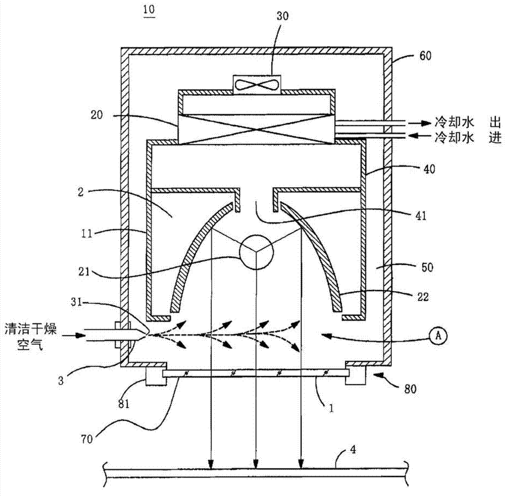
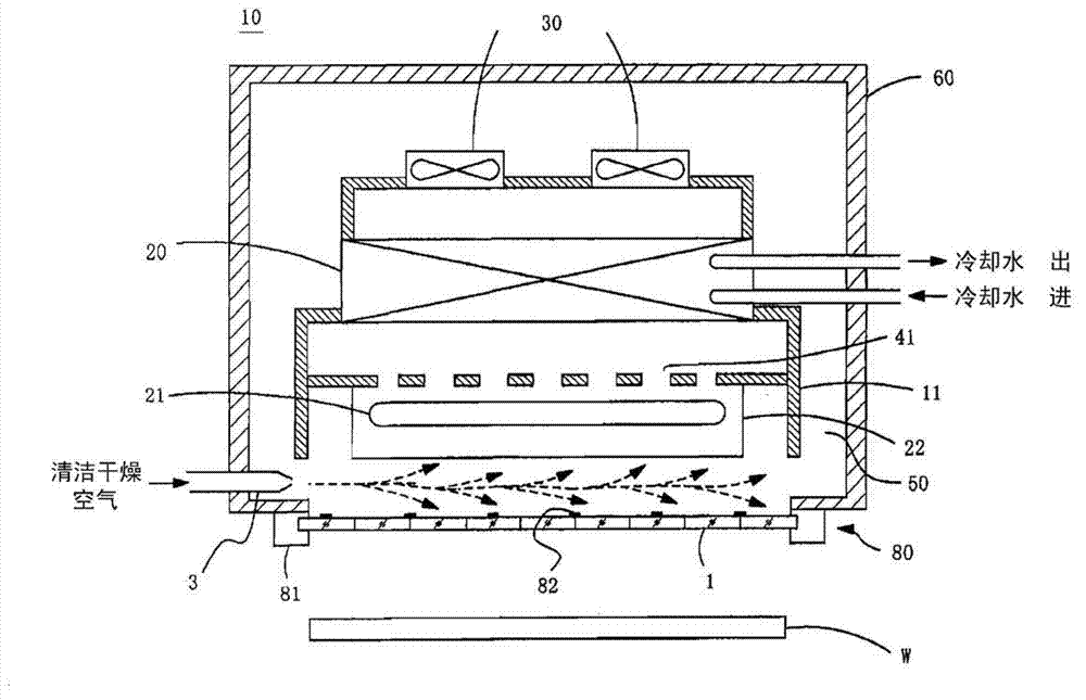
[0080] figure 1 It is a figure which shows the 1st Example of the polarized-light irradiation apparatus of this invention. This figure is a cross-sectional view in a direction perpendicular to the longitudinal direction of the lamp. In addition, in the following examples, although the above Figure 6 The polarized light irradiation device of the structure shown will be described, but the present invention can also be applied to the above-mentioned Figure 8 The polarized light irradiation device with the structure shown.

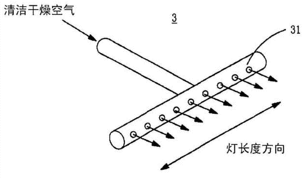
[0081] exist figure 1 in, with Figure 6 The different portion of the conventional device is that the nozzle 3 (air supply mechanism) for supplying gas (clean and dry air) is provided in the space between the mirror 22 and the above-mentioned polarizing element unit 80 . Otherwise the structure is basically the same as Figure 6 The devices described are the same.

[0082] That is, light box 10 is provided with light source part 11, and this light s...


PUM


Abstract

In a polarized light illuminating apparatus that uses a polarizer unit in which a plurality of polarized plates are arranged and configured, an external gas is introduced in a lamp box from the gaps of the boundaries of the polarized plates. The polarized light illuminating apparatus of the present invention is equipped with a light emitting part (2) which possesses a bar-shaped lamp (21) and a cylindrical reflector (22), the polarizer unit (80) is arranged at the light emitting side, and a plurality of polarizers are arranged and configured on the polarizer unit (80). An cooling air is cooled by a cooling machine (20), is transmitted by an air blower (30) to the light emitting side of the above reflector (22) via a ventilation path (50) to cool the lamp (21) and the reflector (22), and is returned to the cooling machine (20). A nozzle (3) used to supply a gas ( for example, a clean and dry gas) is arranged in a space between the reflector (22) and the above polarizer unit (80), and the above space becomes a positive pressure, so that the external gas can be prevented from being introduced into the lamp box (10).

Description

technical field [0001] The present invention relates to a polarized light irradiation device for aligning by irradiating polarized light of a predetermined wavelength to an alignment film of a liquid crystal element, an alignment layer of a viewing angle compensation film, or the like. Background technique [0002] In recent years, in the alignment treatment of the alignment film of the liquid crystal display element represented by the liquid crystal panel, the alignment layer of the viewing angle compensation film, etc., a technology called photo-alignment is used to align by irradiating polarized light with a wavelength in the ultraviolet range. . Hereinafter, a film or layer that generates alignment characteristics by light, such as an alignment film or a thin film provided with an alignment layer, is collectively referred to as a photo-alignment film. [0003] As the size of the liquid crystal panel increases, the photo-alignment film has a larger area, such as a quadra...

Claims


Application Information

Patent Timeline
Patent Type & Authority Applications(China)
IPC IPC(8): G02F1/1337G02B27/28
CPCG02F1/133788A43B7/06A43B11/00A43B23/26
Inventor 筱田和敏
Owner USHIO DENKI KK
Why Eureka
Try Eureka