Apparatus and method for focal plane change measurement

A measurement method, a technique of variation, used in the field of lithography

Active Publication Date: 2013-08-14
SHANGHAI MICRO ELECTRONICS EQUIP (GRP) CO LTD
View PDF5 Cites 7 Cited by
  • Summary
  • Abstract
  • Description
  • Claims
  • Application Information

AI Technical Summary

Problems solved by technology

[0005] The present invention mainly aims at the situation that the mask alignment cannot be controlled by the focusing and leveling sensor, and the zero plane of the vertical measurement sensor of the workpiece table is set to be constant, even if it changes, it will be superimposed on the drift of the focusing and leveling zero plane The idea of ​​focal plane change measurement is to obtain the drift of the zero plane of the focusi

Method used


Image

  • Apparatus and method for focal plane change measurement
  • Apparatus and method for focal plane change measurement
  • Apparatus and method for focal plane change measurement

Examples


Embodiment Construction

[0025] In order to better understand the technical content of the present invention, specific embodiments are given together with the attached drawings for description as follows.

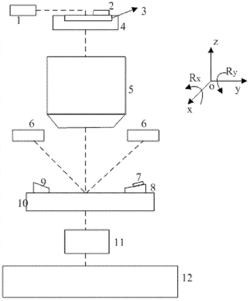
[0026] The focal plane change measuring device proposed by the present invention is as figure 1 As shown, it includes: an optical system 1, a mask mark 2, a mask 3, a mask table 4, a lens 5, a focusing and leveling sensor 6, a reference plate alignment sensor 7, a first workpiece stage reference plate 8, a Two workpiece table reference plate 9, workpiece table 10, workpiece table vertical measurement sensor 11, cornerstone 12. The functions and interrelationships of each subsystem are as follows: optical system 1 emits light source, mask mark 2 is located on mask 3 as mask 3 alignment mark, mask 3 is located on mask table 4, and mask table 4 carries the mask 3 and can move along the y and z directions, the mask mark 2 is imaged by the lens 5, and the focusing and leveling sensor 6 measures the hei...


PUM


Abstract

The invention provides an apparatus and a method for focal plane change measurement. The measurement method comprises the following steps of entering a reference state, calibrating a position of a reference exposure focal plane, updating inclination of a cornerstone relative to the reference exposure focal plane, aligning a reference mask to obtain a reference alignment focal plane change amount and calculate a position of the reference alignment focal plane, measuring the height and a tilt value of a reference leveling point of a workpiece table datum plate by using a focus and level sensor when the workpiece table datum plate moves to the reference position vertically; starting an exposure process, calculating a drift distance of zero plane of the focus and level sensor before wholly leveling the base; aligning a real mask, and calculating a real alignment focal plane change amount to obtain a position of the real alignment focal plane, thereby guaranteeing that the base is always at an optimum focal plane during the exposure.

Description

technical field [0001] The invention relates to the field of photolithography, and in particular to a focal plane variation measuring device and method. Background technique [0002] The lithography device is mainly used in the manufacture of integrated circuits IC or other micro devices. The lithography device exposes through the projection objective lens and transfers the designed mask pattern to the photoresist. As the core component of the lithography device, the object of the projection objective lens The position of the surface and the mirror has an important influence on the image quality of lithography. The purpose of the projection lithography machine is to clearly image the pattern on the mask on the substrate (silicon wafer) coated with photoresist. To achieve this goal, it must be ensured that the exposure area on the substrate is vertically located at the best focal plane of the projection objective lens ( plane with the best exposure quality). [0003] The be...

Claims


Application Information

Patent Timeline
IPC IPC(8): G03F7/20G03F9/00G01M11/02
Inventor 王献英李术新段立峰
Owner SHANGHAI MICRO ELECTRONICS EQUIP (GRP) CO LTD
Why Eureka
Try Eureka