Supercharge Your Innovation With Domain-Expert AI Agents!

Method for dividing workpiece

A technology for processed objects and workbenches, applied in metal processing equipment, manufacturing tools, laser welding equipment, etc., and can solve the problems of non-shrinking and insufficient shrinkage adhesive tape.

Active Publication Date: 2013-08-14
DISCO CORP
View PDF6 Cites 8 Cited by
  • Summary
  • Abstract
  • Description
  • Claims
  • Application Information

AI Technical Summary

Problems solved by technology

[0008] However, even with the technique disclosed in Patent Document 2, there is concern that shrinkage due to external stimuli may be insufficient or may not shrink depending on the material and thickness of the adhesive tape, and further improvement is desired.

Method used


Image

  • Method for dividing workpiece
  • Method for dividing workpiece
  • Method for dividing workpiece

Examples


Embodiment Construction

[0042] The present invention is a method of dividing a to-be-processed object in which a plurality of intersecting planned dividing lines are set along the planned dividing line. Hereinafter, embodiments of the present invention will be described in detail with reference to the drawings.

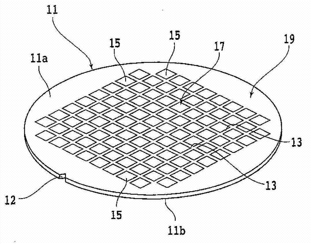
[0043] figure 1 This is a diagram showing a semiconductor wafer 11 (hereinafter, also simply referred to as “wafer 11”) as an embodiment of the workpiece. The wafer 11 is composed of, for example, a silicon wafer having a thickness of 700 μm. The wafer 11 has a plurality of intersecting planned dividing lines (spacers) 13 formed in a grid on the surface 11a, and is divided by the plurality of planned dividing lines 13 Devices 15 are respectively formed in the plurality of regions.

[0044] The wafer 11 thus configured includes a device region 17 in which the device 15 is formed, and an outer peripheral remaining region 19 surrounding the device region 17. A notch 12 is formed on the outer periph...


PUM


Abstract

The present invention provides a method for dividing a workpiece. By preventing a divided chip and a DAF from contacting, the defect and damage of the chip, and the rejoin of the DAF can be prevented reliably. The method comprises a step of forming a hump, in which a retaining workbench and a frame retaining member move relatively along a vertical direction to release the jack-up of the retaining workbench relative to the frame retaining member, and the residual parts of an adhering belt, which are formed by expanding the adhering belt, form the hump that is humped towards the surface side of the adhering belt at the periphery of the workpiece; a step of overturning the hump, in which, after the hump forming step, the hump is sucked from the back side of the adhering belt via a sucking member, so that the hump is protruded to the back side of the adhering belt to thereby form a backside hump; a step of cutting residues, in which, after the hump overturning step, the backside hump is clamped by a clamping member, so that the parts at the inner side of the backside hump are adhered with each other to thereby cut the residual parts of the adhering belt.

Description

Technical field [0001] The present invention relates to a method of dividing a workpiece such as a semiconductor wafer. Background technique [0002] In the past, for example, as disclosed in Patent Document 1, a processing object pasted on an adhesive tape was divided by a dividing device after a modified layer, a laser processing groove, a cutting groove, etc. were formed along the planned dividing line. Into individual chips. [0003] Patent Document 1 discloses a technique of dividing the workpiece by applying an external force to the workpiece by expanding the adhesive tape to which the workpiece is pasted. After the adhesive tape stretched by the expansion is released from the expanded state, the stretched part forms the remaining part. This remaining part is in an untensioned and relaxed state, so there is a concern that adjacent chips after division may come into contact with each other, resulting in chipping or breakage. [0004] Furthermore, when attaching DAF (die-attac...

Claims


Application Information

Patent Timeline
IPC IPC(8): H01L21/78H01L21/683B23K26/36
CPCH01L21/6836H01L21/78
Inventor 服部笃川口吉洋淀良彰
Owner DISCO CORP
Features
  • R&D
  • Intellectual Property
  • Life Sciences
  • Materials
  • Tech Scout
  • Unparalleled Data Quality
  • Higher Quality Content
  • 60% Fewer Hallucinations
Learn More