Downlink pilot frequency collocation method, base station and mobile terminal
A pilot configuration and mobile terminal technology, applied in electrical components, wireless communication, etc., can solve the problems of high CSI-RS resource occupation and inflexible configuration, and achieve the effect of avoiding uncertain problems and reducing overhead
- Summary
- Abstract
- Description
- Claims
- Application Information
AI Technical Summary
Problems solved by technology
Method used
Image
Examples
Embodiment 1
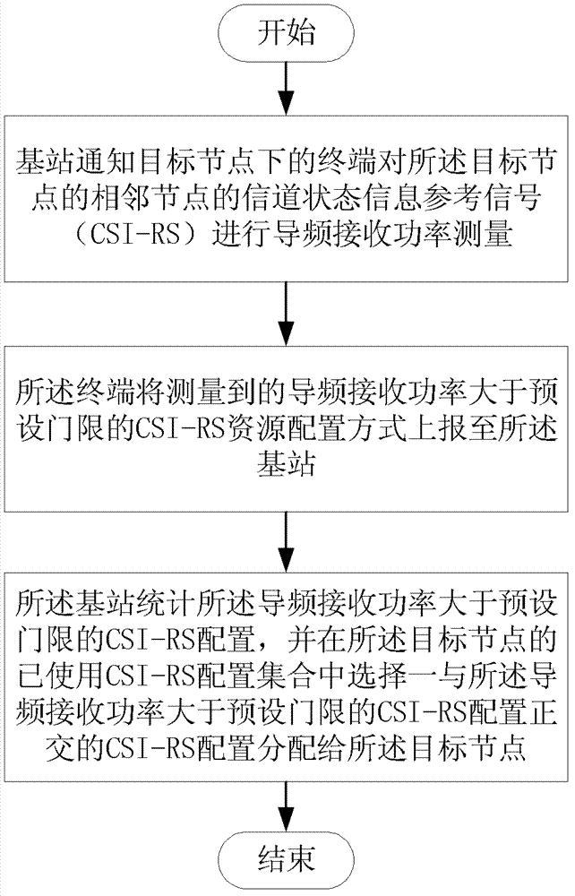
[0055] like Figure 4 As shown, the process of adding a new node in the existing network.
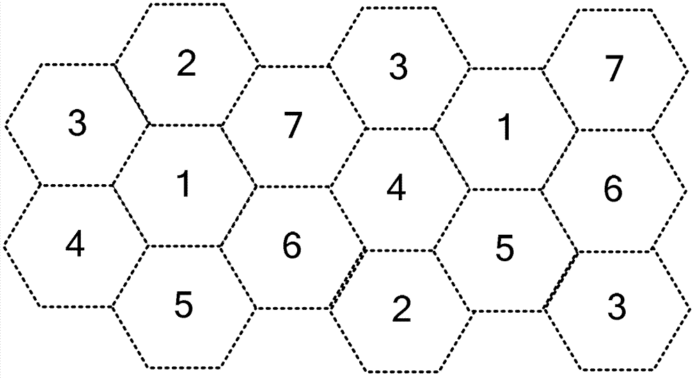
[0056] exist figure 1 Introducing a new node anywhere in the network shown involves the following steps:
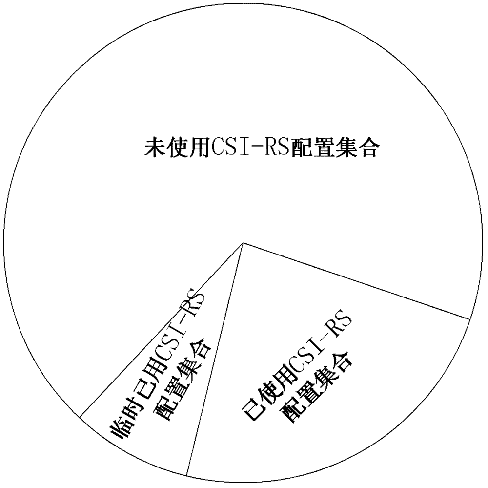
[0057] S101, a new node is established, and the used CSI-RS configuration set and the unused CSI-RS configuration set of adjacent nodes or nodes in the entire area are exchanged, and the combination of the two sets is initialized to all CSI-RS configurations specified in the protocol.
[0058] S102: Select a configuration orthogonal to the used CSI-RS configuration from the unused CSI-RS configuration set as the temporary CSI-RS configuration of the node, and add the temporary configuration to the temporary used CSI-RS configuration set .
[0059] S103, the base station notifies the UE under the current node to measure the CSI-RS of the adjacent node, and the terminal selects and reports the CSI-RS configuration with the RSRP value greater than the threshold T according to the t...
Embodiment 2
[0066] like Figure 5 As shown, the difference from Embodiment 1 is that the objects configured in this embodiment are nodes that already exist in the existing network but need to be re-optimized for configuration. Such operations are initiated, for example, when the CSI measurement performance of a node is degraded or the CSI-RS configuration in the allocation area needs to be re-optimized due to changes in other conditions. The basic steps are as follows:
[0067] S201, the base station side decides according to channel information, UE performance statistics, etc., or initiates actions of re-measurement and configuration optimization for the CSI-RS configuration of the current node, or periodically, or through a configuration instruction.
[0068] S202, the base station side selects a configuration orthogonal to the used CSI-RS configuration set from the unused CSI-RS configuration set as the temporary CSI-RS configuration of the node, and notifies other nodes to add this t...
Embodiment 3
[0076] User-level CSI-RS configuration process.
[0077]The configuration process is similar to Embodiment 1 and Embodiment 2, except that the CSI-RS configuration in this embodiment is a user-level configuration, that is, a strategy is used for each user to perform the CSI-RS configuration. In this manner, the CSI-RS configuration sets on the time-frequency resources where each UE is located may be different.
[0078] S301, in the initial state, the base station selects a configuration orthogonal to the used CSI-RS configuration from the unused CSI-RS configuration set of the UE as the temporary CSI-RS configuration of the user, and adds this temporary configuration to the temporary used CSI -RS configuration collection.
[0079] S302 , the base station notifies the UE of the measurement set, including the frequency domain location, the cell identifier, and the CSI-RS configuration, and the UE measures and reports the CSI-RS configuration whose RSRP value is greater than the...
PUM
 Abstract
Description
Claims
Application Information
 - R&D
- Intellectual Property
- Life Sciences
- Materials
- Tech Scout
- Unparalleled Data Quality
- Higher Quality Content
- 60% Fewer Hallucinations
Browse by: Latest US Patents, China's latest patents, Technical Efficacy Thesaurus, Application Domain, Technology Topic, Popular Technical Reports.
© 2025 PatSnap. All rights reserved.Legal|Privacy policy|Modern Slavery Act Transparency Statement|Sitemap|About US| Contact US: help@patsnap.com


