Method for controlling light modulation device

A technology of a dimming device and a control method, which is applied in the field of circuits, can solve problems such as inconvenience, and achieve the effect of simple communication and easy standardization

Active Publication Date: 2013-08-14
INVENTRONICS HANGZHOU
View PDF5 Cites 1 Cited by
  • Summary
  • Abstract
  • Description
  • Claims
  • Application Information

AI Technical Summary

Problems solved by technology

[0008] This shows that above-mentioned existing mode obviously still has inconvenience and defective, and needs to be further improved
In order to solve the above problems, related fields have tried their best to find a solution, but no applicable method has been developed for a long time.

Method used


Image

  • Method for controlling light modulation device
  • Method for controlling light modulation device
  • Method for controlling light modulation device

Examples


Embodiment 1

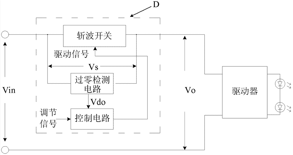
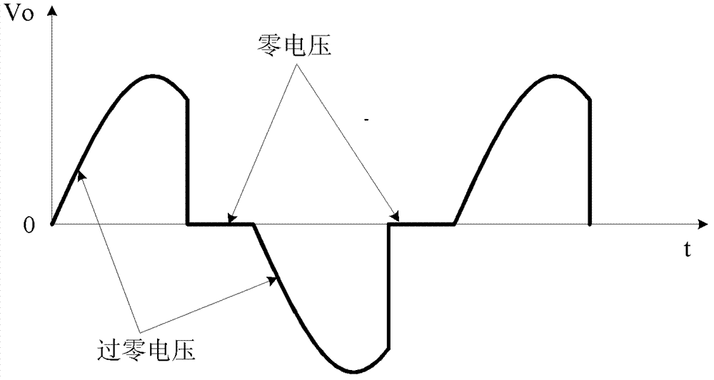
[0047] In order to solve the above problems, the present invention provides a control method of a dimming device, see Figure 5 , the dimming device includes a two-wire dimmer D and a post-stage driver connected to the rear stage of the two-wire dimmer D, the two-wire dimmer D also includes a chopping switch, and its input side It can continuously receive an AC voltage; the chopping switch only works in a chopping state in a part of the cycle of the AC voltage, and works in a fully conducting state in other cycles, and the post-stage driver includes an impedance matching circuit and an impedance matching control circuit. The method for controlling the AC voltage received by the two-wire dimmer by the dimming device is as follows: when the two-wire dimmer D receives an adjustment signal, the chopper switch first enters the modulation cycle under the action of the driving signal Perform frequency modulation on the AC voltage, the output terminal of the two-wire dimmer generates...

Embodiment 2

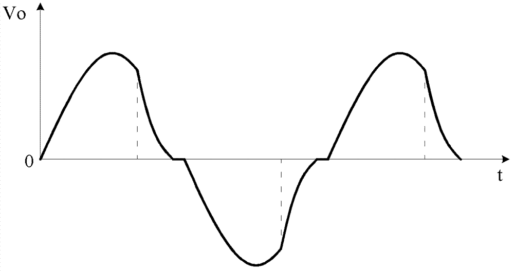
[0053] Based on the first embodiment, see Figure 7 , the two-wire dimmer in the dimming device includes a chopper switch and a step-down unit, the step-down unit is connected in parallel between the input end and the output end of the chopper switch, and during the modulation cycle, The step-down unit and the chopper switch are turned on alternately at high frequency; during the chopping cycle, the step-down unit is always in an off state.

[0054] Combine now Figure 8 The control method of the dimming device including the step-down unit is described as follows:

[0055] In the modulation cycle, the step-down unit and the chopper switch are alternately turned on as follows: when the chopper switch is turned on under the drive of the high-frequency drive signal, the step-down unit is Off state, at this time, the step-down unit does not provide a current path for the input and output terminals of the two-wire dimmer, and the voltage at the output terminal of the two-wire dim...

Embodiment 3

[0060] Based on the second embodiment, see Figure 9 , the structures of the chopper switch and the step-down unit in the dimming device and the corresponding control method of the dimming device are as follows:

[0061] The chopper switch at least includes a first switching tube S1, a second switching tube S2, a first diode D1, and a second diode D2, and the control terminals of the first switching tube S1 and the second switching tube S2 are The same drive signal is connected, the current output ends of the first switching tube S1 and the second switching tube S2 are connected to each other, and the anodes of the first diode D1 and the second diode D2 are connected to the The current output terminals (out) of the first switching tube S1 and the second switching tube S2, the cathode of the first diode D1 is connected to the current input terminal (in) of the first switching tube S1, and the second two The cathode of the pole tube D2 is connected to the current input terminal...


PUM


Abstract

The invention discloses a method for controlling a light modulation device. When a two-line light modulator receives a modulation signal, a chopping switch firstly enters a modulation period to modulate the frequency or the amplitude of alternating voltage under the action of a driving signal, so that frequency modulation voltage or amplitude modulation voltage is produced and then output to a backward-stage driver; then the two-line light modulator enters a chopping period to chop the alternating voltage; and an impedance matching control circuit controls an impedance matching circuit to work in a low impedance state within a maximum chopping phase angle in chopping voltage of each chopping period according to the judgment whether the two-line light modulator outputs the frequency modulation voltage or the amplitude modulation voltage. According to the method for controlling the light modulation device, when the two-line light modulator exists at a forward stage, the chopping switch in the two-line light modulator informs the impedance matching control circuit in the backward-stage driver of controlling the impedance matching circuit to work in the low impedance state within the maximum chopping phase angle in chopping voltage of each chopping period before entering the chopping state, so that the cooperative work of the chopping switch and the impedance matching circuit is realized.

Description

technical field [0001] The invention belongs to the field of circuits, and in particular relates to a dimming device and a control method thereof. Background technique [0002] The existing two-wire dimmer is usually connected between the power grid (Hot) and the load end (Dimmed Hot). Since there are only two wires between the dimmer and the power grid and the load end, it is named a two-wire dimmer. [0003] When the two-wire dimmer has an output of continuous zero voltage in half of the AC power cycle, the output voltage Vo of the two-wire dimmer is called the chopping voltage. Correspondingly, the chopping switch works in the chopping state. At the same time, The phase angle corresponding to the zero voltage duration in the output voltage Vo of the two-wire dimmer in half an AC cycle is the chopping phase angle. Two-wire dimmers usually use semiconductor power devices such as MOS transistors, IGBTs (insulated gate bipolar transistors), or thyristors as chopper switches,...

Claims


Application Information

Patent Timeline
Patent Type & Authority Applications(China)
IPC IPC(8): H05B37/02
Inventor 姜德来刘伟熊代富
Owner INVENTRONICS HANGZHOU
Why Eureka
Try Eureka