Electrical or electronic safety module

An electronic safety and electrical technology, applied in the field of electrical or electronic safety circuits, can solve problems such as power limitation

Inactive Publication Date: 2013-08-14
EHNDRESS KHAUZER GMBKH KO KG
View PDF13 Cites 5 Cited by
  • Summary
  • Abstract
  • Description
  • Claims
  • Application Information

AI Technical Summary

Problems solved by technology

[0006] The above-described methods of limiting the surface temperature have in principle the disadvantage that the power of the individual components or areas must be strongly limited as a function of the upstream or current-limiting resistors

Method used


Image

  • Electrical or electronic safety module
  • Electrical or electronic safety module
  • Electrical or electronic safety module

Examples


Embodiment Construction

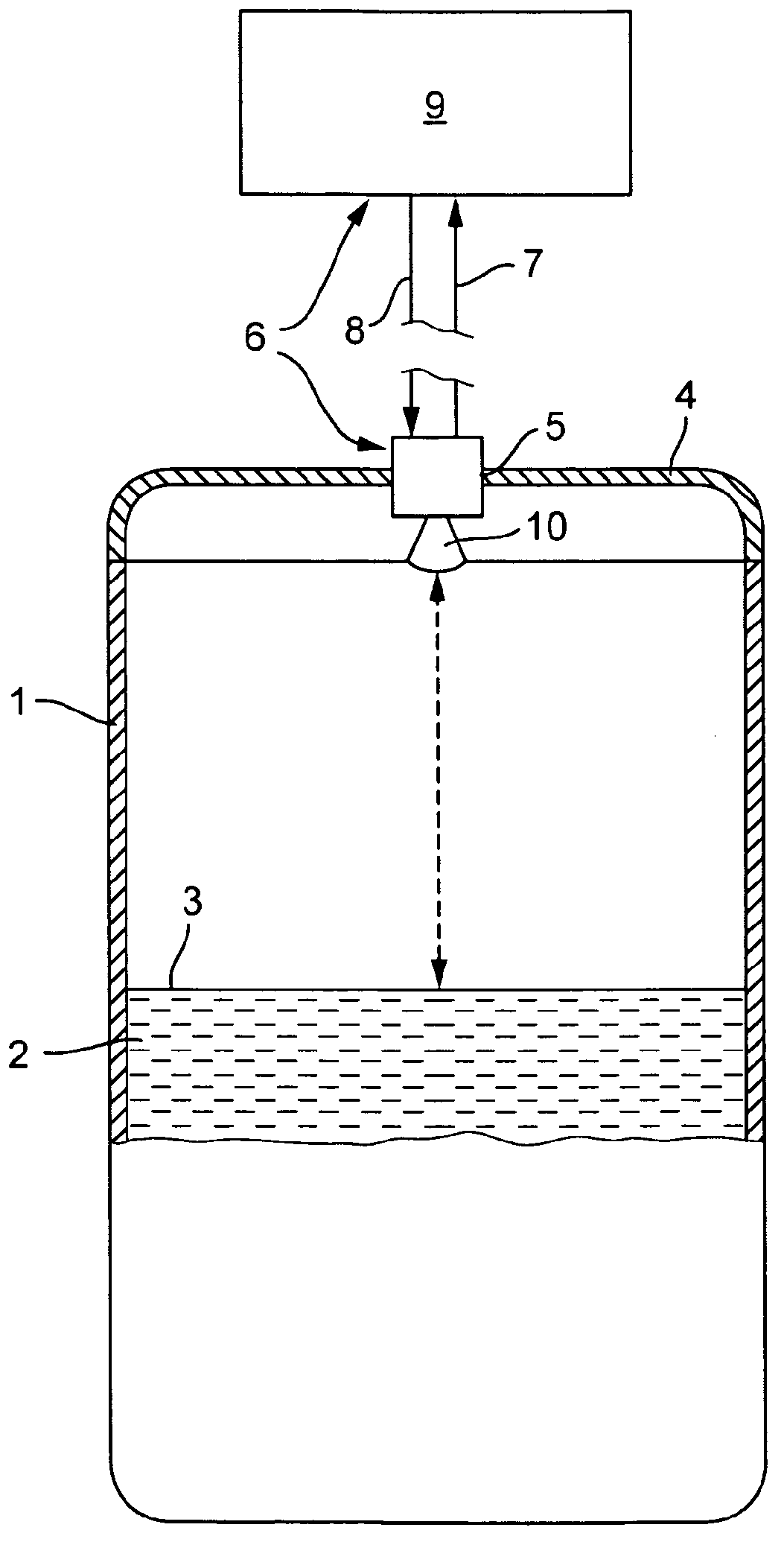
[0036] figure 1 A schematic representation of a fill level measuring device 6 is shown, in which case the solution of the invention is preferably applied. Filling substance 2 is stored in container 1 . The fill level 3 of the filling substance 2 in the container 1 is determined by means of the fill level measuring device 6 using the transit time method. In the illustrated case, the antenna unit 10 with the signal generating unit, the transmitting unit and the receiving unit is spatially separated from the control / evaluation unit 9 . Data exchange and current supply between the signal-generating high-frequency module 12 on the one hand and the sensor electronics 9 on the other hand take place via connecting lines 7 , 8 . Of course, with regard to the invention it is also possible to use a compact device as fill level measuring device 6 .

[0037] The antenna unit 10 is mounted in the opening 5 in the lid 4 of the container 1 . Via the antenna unit 10 , the measurement sign...


PUM


Abstract

A time triggered crowbar, which is so embodied that it monitors the on-time of at least one downstream electronic component and the period of clocking and therewith the power supply in such a manner that a predetermined maximum allowable surface temperature of the at least one downstream component is not exceeded in the explosion endangered area.

Description

technical field [0001] The invention relates to an electrical or electronic safety circuit which is connected via at least one supply line to at least one component connected downstream in an explosion-endangered area and which is connected by means of the type of ignition protection required in the explosion-endangered area The function monitors the power supplied via the supply line to protect such components, wherein the at least one downstream component is operated by being timed in such a way that its on-time is less than the timing period. Background technique [0002] Especially in the field of automation technology, whether plant or process automation technology, the type of ignition protection of devices installed in explosion-endangered areas plays an important role. The type of ignition protection shall exclude the risk of an ignition source capable of triggering an explosion in an explosive or explosion-endangered atmosphere. Types of ignition protection used in...

Claims


Application Information

Patent Timeline
Patent Type & Authority Applications(China)
IPC IPC(8): G01F15/06G01F23/00G01F23/284
CPCG01F23/284G01F15/06G01F23/0061H02H9/008G01F23/80
Inventor 罗兰·格罗青格得特勒夫·拉明
Owner EHNDRESS KHAUZER GMBKH KO KG
Why Eureka
Try Eureka