Foundation-free rapidly installed and transformed stirring station
A mixing station and basic technology, applied in mixing plants, clay preparation equipment, mixing operation control, etc., can solve the problems of inconvenient transfer of mixing stations, complicated and cumbersome installation, high construction costs, etc., to save relocation costs, convenient transportation, and quick installation Effect
- Summary
- Abstract
- Description
- Claims
- Application Information
AI Technical Summary
Problems solved by technology
Method used
Image
Examples
Embodiment 1
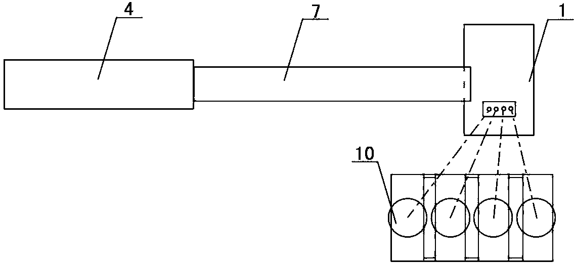
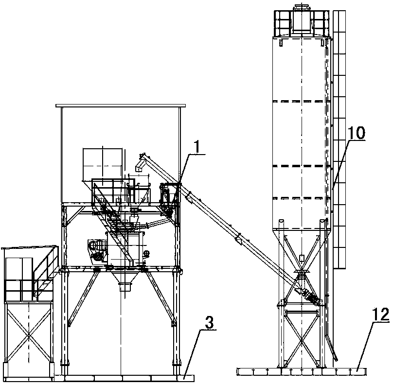
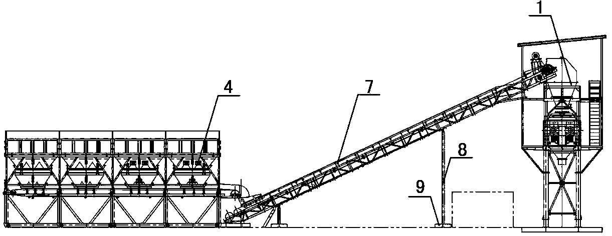
[0065] Embodiment one sees figure 1 , figure 2 , image 3 As shown, this foundation-free quick installation transition mixing station includes a main station 1, a batching machine 4, a belt conveyor 7, a powder silo 10 and a basic structure. The basic structure consists of a main station foundation 3, a batching machine foundation 6, The belt conveyor foundation 9 and the powder silo foundation are composed of four independent foundations, and the design principles of the foundation are non-settling, anti-overturning, transportable, and moderate cost. Because the powder silo not only has a large load but also has a high center of gravity, it is listed as The key point of the design of the present invention, according to this principle, designed three general layout schemes suitable for different needs: the powder silo in embodiment 1 adopts a linear arrangement of the scheme: the small foundations of the powder silo are arranged in parallel and spaced apart In a row, the ce...
Embodiment 2
[0076] Embodiment two see Figure 21 As shown, the difference from Embodiment 1 is that the powder silos are arranged in an arc shape according to the second scheme: the center points of the silo bodies of the plurality of powder silos 10 are arc-shaped, and are distributed in one of the master stations. side, wherein the outermost powder bin small foundation is perpendicular to other powder bin small foundations, the number of powder bins 10 is not more than five, and the powder bin small foundation 12 consists of powder bin longitudinal beam 12.1, powder bin beam 12.2 It is made of screw joints and arranged on one side of the main station 1. The longitudinal beam of the powder hopper small foundation of one of the powder hoppers is parallel to the feeding and transportation direction of the belt conveyor 7, and the other small powder hopper foundations are arranged in parallel and at intervals , the longitudinal beam of the powder silo is perpendicular to the feeding and tra...
Embodiment 3
[0078] Embodiment three see Figure 24 , Figure 25 As shown, the difference from Embodiment 1 and Embodiment 2 is that the powder silo is arranged in a rectangle according to the third scheme: the small foundations 12 of the powder silo are arranged in two rows in parallel and spaced apart, and are distributed on both sides of the main station. The number of powder silos 10 is not more than six, and the small foundation 12 of the powder silo is formed by screwing the longitudinal beam 12.1 of the powder silo and the beam 12.2 of the powder silo, arranged in parallel in two rows and distributed symmetrically to the main station 1 On both sides of the main station 1, the longitudinal beam 12.1 of the powder silo is perpendicular to the feeding and transportation direction of the belt conveyor 7, see Figure 28 As shown, the adjacent powder bin longitudinal beams 12.1 are connected by screwed connecting beams 13, and the powder bin frame body 11 is screwed on the powder bin con...
PUM
 Abstract
Description
Claims
Application Information
 - R&D
- Intellectual Property
- Life Sciences
- Materials
- Tech Scout
- Unparalleled Data Quality
- Higher Quality Content
- 60% Fewer Hallucinations
Browse by: Latest US Patents, China's latest patents, Technical Efficacy Thesaurus, Application Domain, Technology Topic, Popular Technical Reports.
© 2025 PatSnap. All rights reserved.Legal|Privacy policy|Modern Slavery Act Transparency Statement|Sitemap|About US| Contact US: help@patsnap.com


