Cathode protection method for heat exchanger subassembly and heat exchanger subassembly

A cathodic protection, heat exchanger technology, applied in damage protection, heat exchange equipment, lighting and heating equipment, etc., to achieve stable water flow noise, reduce water flow noise, and simple settings

Active Publication Date: 2013-08-21
GUANGDONG MACRO GAS APPLIANCE
View PDF4 Cites 5 Cited by
  • Summary
  • Abstract
  • Description
  • Claims
  • Application Information

AI Technical Summary

Problems solved by technology

[0004] After the actual product inspection, although the surface treatment of the heat exchange tube prolongs the service life of the heat exchanger, the problem of perforation and water leakage of the heat exchange tube has always existed. This problem has plagued the water heater industry for several years and has not been effectively resolved.

Method used


Image

  • Cathode protection method for heat exchanger subassembly and heat exchanger subassembly
  • Cathode protection method for heat exchanger subassembly and heat exchanger subassembly
  • Cathode protection method for heat exchanger subassembly and heat exchanger subassembly

Examples


Embodiment 1

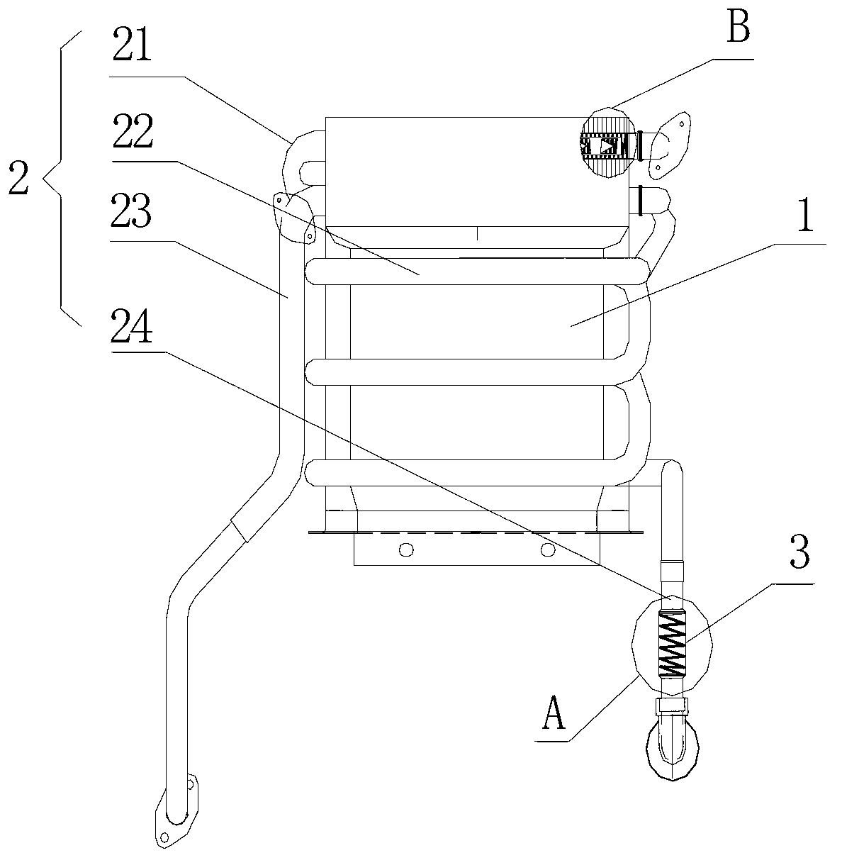
[0051] Such as figure 2 As shown, a heat exchanger part assembly based on the above-mentioned cathodic protection method, which is a main heat exchanger part assembly, includes: a heat exchanger shell 1, a heat exchange tube 2 connected to the heat exchanger shell 1, and A cathodic protection device 3 connected to the inner wall of the heat exchange tube 2 .

[0052] Wherein, the heat exchange tube 2 includes: a main heat exchange tube 21 inserted through the upper part of the heat exchanger shell 1, a coil tube 22 connected to one end of the main heat exchange tube 21 and wound on the heat exchanger shell 1, connected to The water outlet pipe 23 at one end of the main heat exchange pipe 21 and the water inlet pipe 24 connected to one end of the coil pipe 22 .

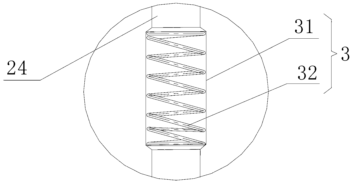
[0053] Such as image 3 As shown, the cathodic protection device 3 includes: an expansion tube 31 integrally formed with the water inlet tube 24 and an anode spring 32 arranged in the expansion tube 31 . In particu...

Embodiment 2

[0058] Such as Figure 5 As shown, a heat exchanger unit based on the above-mentioned cathodic protection method includes: a heat exchanger shell 4 with a smoke inlet 41 and a smoke exhaust port 42, and the condensation heat exchange device arranged in the heat exchanger shell 4 tube 5, and the cathodic protection device 3 connected to the inner wall of the condensing heat exchange tube 5.

[0059] The structure of a heat exchanger unit provided in this embodiment is basically the same as that of Embodiment 1, the difference is that:

[0060] 1. The main body of the heat exchanger part is a condensation heat exchange device. The smoke inlet 41 is set on the bottom side of the heat exchanger shell 1, and the smoke exhaust port 42 is set on the top of the heat exchanger shell 1. The condensing heat exchange tube 5 is arranged in the heat exchanger shell 4 in a spiral shape.

[0061] 2. The cathodic protection device 3 is an independent structure, which is screwed on the water ...


PUM


Abstract

The invention relates to an ordinary heat exchanger with tubular passages and discloses a cathode protection method for a heat exchanger subassembly. The cathode protection method is characterized in that an anode material with the activity superior to that of a pipe body is connected with the inner wall of a water pipe in the heat exchanger subassembly, and when the water pipe of the heat exchanger is corroded, the anode material automatically releases electrons to the corroded part so as to protect the water pipe of the heat exchanger. The invention further provides the heat exchanger subassembly based on the cathode protection method. The heat exchanger subassembly comprises a heat exchanger shell and a heat exchanging pipe. The heat exchanger subassembly is characterized in that a cathode protection device is connected to the inner wall of the heat exchanging pipe; and the heat exchanger subassembly is a main heat exchanger or a condensing heat exchanger. Compared with the prior art, the cathode protection method for the heat exchanger subassembly and the heat exchanger subassembly have the advantage that phenomena of perforation and water leakage of the heat exchanging pipe are solved by carrying out electrochemical corrosion protection from the inner part of the heat exchanging pipe.

Description

technical field [0001] The invention relates to a general heat exchanger with a tubular channel, in particular to a cathodic protection method for a heat exchanger part and a heat exchanger part. Background technique [0002] The heat exchanger is an essential element of a gas water heater. At present, the commonly used heat exchanger materials are mainly copper materials and aluminum alloy materials. However, whether it is a copper heat exchanger or an aluminum alloy heat exchanger, there will be pitting corrosion after a period of use, and there will be water pipe perforation and water leakage, such as figure 1 shown. Especially in Shanxi and Shaanxi regions, this phenomenon of water pipe perforation is more serious. [0003] As we all know, the corrosion of heat exchanger is mainly electrochemical corrosion, and the heat exchange tube is the key part of corrosion protection. Since the heat exchanger works in a hot and humid environment, condensed water exists on the su...

Claims


Application Information

Patent Timeline
Patent Type & Authority Applications(China)
IPC IPC(8): C23F13/06F28F19/00
Inventor 余少言仇明贵马海川
Owner GUANGDONG MACRO GAS APPLIANCE
Why Eureka
Try Eureka