
Ureteroscope dilatation balloon

A ureteroscope and balloon technology, applied in the field of medical devices, can solve problems such as ureteral perforation, rupture, and difficult surgery, and achieve the effects of reducing labor intensity, reducing pain, and shortening operation time

Active Publication Date: 2021-12-21
THE SECOND HOSPITAL OF SHANDONG UNIV
View PDF11 Cites 0 Cited by
  • Summary
  • Abstract
  • Description
  • Claims
  • Application Information

AI Technical Summary

Problems solved by technology

When the existing ureteroscope uses a balloon to dilate the ureteral stenosis, it cannot be dilated under the direct vision of the endoscope, but can only be dilated under X-ray positioning. Since it cannot be dilated under direct vision, it is possible Cause ureter perforation, rupture, etc., the operation is difficult, and the operation effect is not very ideal

Method used


Image

  • Ureteroscope dilatation balloon
  • Ureteroscope dilatation balloon
  • Ureteroscope dilatation balloon

Examples


Embodiment 1

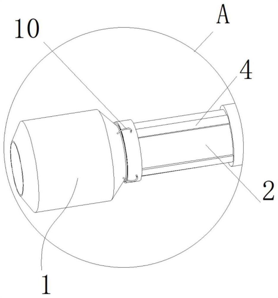
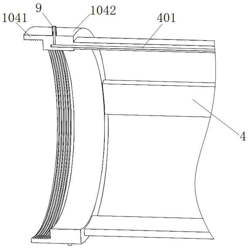
[0033] Such as Figure 1-Figure 9 As shown, a ureteroscope expansion balloon includes a balloon body 1, and the balloon body 1 is slidably sleeved on the front end of the ureteroscope; the ureteroscope includes a first cylinder 2 and a second cylinder 3, and the first cylinder 2 It is fixedly connected with the second cylinder 3 in turn, and the first cylinder 2 and the second cylinder 3 are arranged coaxially. The inner diameter of the first cylinder 2 is the same as that of the second cylinder 3. The first cylinder 2 The outer diameter is smaller than the outer diameter of the second cylinder 3 . The first cylinder body 2 and the second cylinder body 3 are fixedly connected by welding, and can also be integrally formed during processing. By designing the outer diameter of the second cylindrical body 3 to be larger than the outer diameter of the first cylindrical body 2, a height difference can be formed between the second cylindrical body 3 and the first cylindrical body 2,...

Embodiment 2

[0045] This embodiment is further modified on the basis of the first embodiment, and the same parts will not be repeated.

[0046] The end of the protective tube 11 away from the first cylindrical body 2 is provided with a connecting plate 12, the connecting plate 12 is arranged along the length direction of the protective tube 11, the connecting plate 12 is provided with a first installation hole and a second installation hole, and the first installation hole A first positioning rod 13 is slidingly installed, and a second positioning rod 14 is slidingly installed in the second mounting hole. The first positioning rod 13 is sleeved with a first spring 16, and the second positioning rod 14 is sleeved with a second spring 17. , the first spring 16 and the second spring 17 are compression springs, and the connecting cylinder 5 is provided with a positioning hole that is all adapted to the first positioning rod 13 and the second positioning rod 14; when the first positioning rod 13...


PUM


Abstract

The invention discloses an ureteroscope dilatation balloon. The ureteroscope dilatation balloon comprises a balloon body, wherein the balloon body is arranged at the front end of a ureteroscope in a sliding and sleeving mode; the ureteroscope comprises a first barrel and a second barrel, the first barrel and the second barrel are sequentially and fixedly connected and are coaxially arranged, the inner diameter of the first barrel is the same as that of the second barrel, the outer diameter of the first barrel is smaller than that of the second barrel, sliding holes are formed in the second barrel in the axis direction, the first barrel is arranged on the balloon body in a sliding mode, connecting rods are arranged on the balloon body, each connecting rod penetrates through the corresponding sliding hole and is in sliding fit with the corresponding sliding hole, each air inlet channel is formed in the corresponding connecting rod in the axis direction, and the air inlet channels communicate with the balloon body. According to the ureteroscope dilatation balloon, a narrow part can be dilated under endoscope direct view, and ureter perforation, rupture and the like are avoided.

Description

technical field [0001] The invention relates to the technical field of medical instruments, in particular to an expansion balloon for ureteroscopes. Background technique [0002] Ureteroscopy refers to various operations such as ureteral and renal tissue biopsy, lithotripsy, electrocautery, and internal incision of ureteral stenosis by placing an endoscope through natural human passages such as the urethra and bladder. It is mainly used to treat stones, polyps or strictures in the middle and lower ureter, and can also be used to diagnose diseases such as renal pelvis and ureteral tumors. Ureteroscopic surgery has no incision, less trauma, and quick recovery, so it is favored by doctors and patients, and it has played an increasingly important role in the treatment of ureteral diseases, especially ureteral calculi. When the existing ureteroscope uses a balloon to dilate the ureteral stricture, it cannot be dilated under the direct vision of the endoscope, but can only be dil...

Claims


Application Information

Patent Timeline
Patent Type & Authority Applications(China)
IPC IPC(8): A61M29/02A61B1/307A61B1/012
CPCA61M29/02A61B1/307A61B1/012A61M2210/1089A61M2210/005
Inventor 常海洋王维李玉亮陈超
Owner THE SECOND HOSPITAL OF SHANDONG UNIV
Learn More