Pulse vortexing defect quantitative detection method and detection system

A quantitative detection method and pulsed eddy current technology, applied in the direction of material magnetic variables, can solve the problems of high cost, quantitative estimation of defects, and inability to quantitatively estimate the size of defects, and achieve the effect of low cost, simple method and process, and easy operation.

Inactive Publication Date: 2013-08-21
UNIV OF ELECTRONIC SCI & TECH OF CHINA
View PDF6 Cites 29 Cited by
  • Summary
  • Abstract
  • Description
  • Claims
  • Application Information

AI Technical Summary

Problems solved by technology

[0004] Li Luming of Tsinghua University and others proposed a resonant eddy current detection method for surface cracks, the patent number is CN200610113299.7, which uses a resonant circuit to generate a pulse resonance signal, excites the sensor coil, and obtains the eddy current field through the detection coil to determine the crack defect. Exist, but the problem is that it can only identify the existence of defects, but cannot quantitatively estimate the size of defects
Wang Ping of Nanjing University of Aeronautics and Astronautics proposed an integrated detection syste

Method used


Image

  • Pulse vortexing defect quantitative detection method and detection system
  • Pulse vortexing defect quantitative detection method and detection system
  • Pulse vortexing defect quantitative detection method and detection system

Examples


Example Embodiment

[0040] Embodiments of the present invention will be further described below in conjunction with the accompanying drawings.

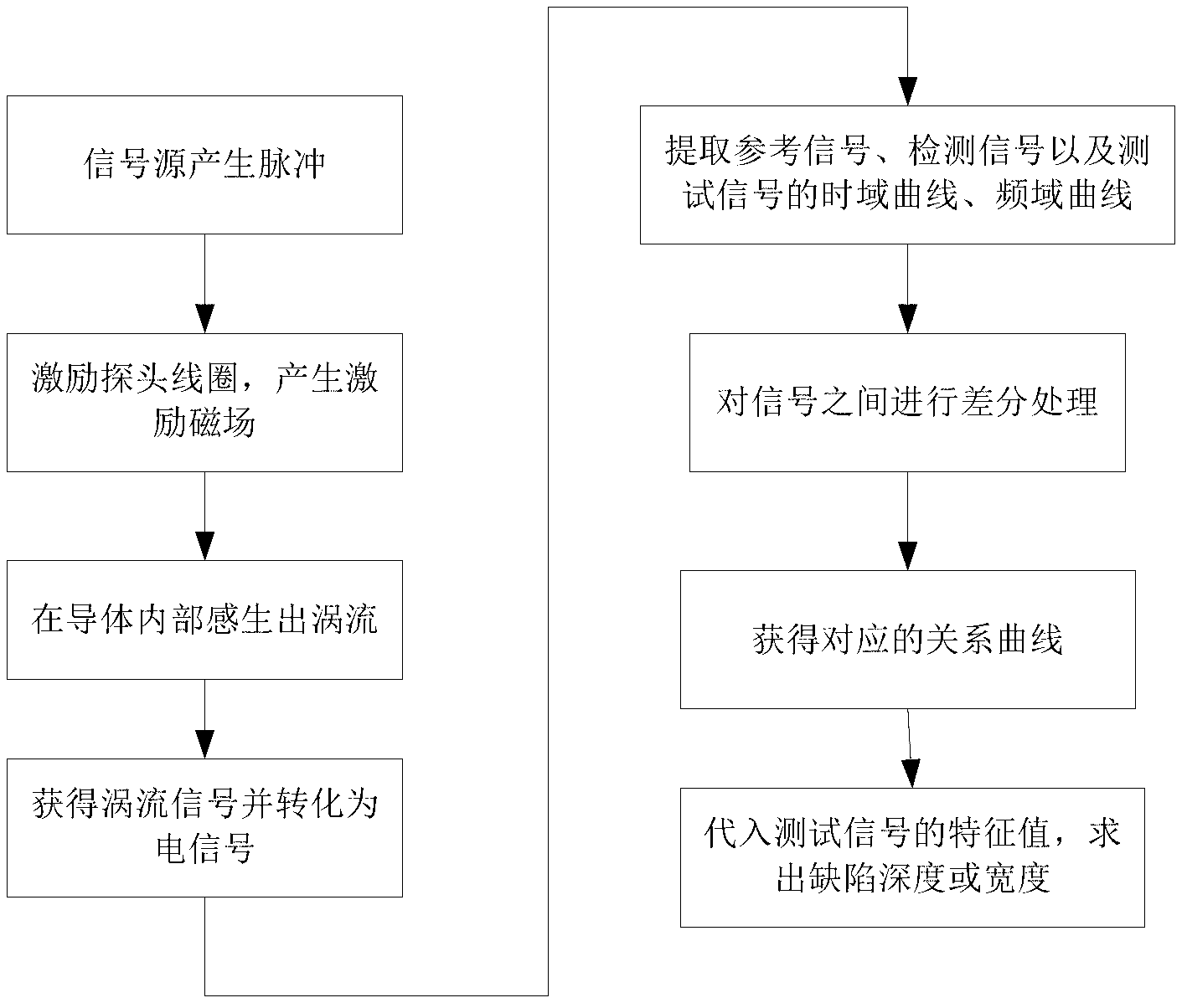
[0041] The flow chart of the pulsed eddy current defect quantitative detection method in the embodiment of the present invention is as follows figure 1 shown, including:

[0042] Step 1. When the depth or width of the defect is known, obtain the algebraic expression of the relationship curve between the peak value of the time-domain signal difference between the response signals and the depth or width of the surface defect or the fundamental frequency of the frequency-domain signal between the response signals The algebraic expression of the relationship curve between the differential peak value and the depth or width of the surface defect, specifically includes the following sub-steps:

[0043] S11, generating a pulse excitation signal with adjustable frequency and duty ratio;

[0044] S12. Excite the probe coil to generate an excitation magnetic field,...


PUM


Abstract

The invention discloses a pulse vortexing defect quantitative detection method and a detection system. The detection method mainly comprises the followings steps of: step 1, obtaining a relation curve algebraic expression of a time domain signal difference peak value among response signals and surface defect depth or width or a relation curve algebraic expression of a frequency domain signal fundamental frequency difference peak value among the response signals and the surface defect depth or width under the condition with known defect depth or width of a tested piece; and step 2, carrying out quantitative evaluation on the defect depth or width of the tested piece, thus obtaining a time domain signal curve or a frequency domain signal curve of a test signal, and further obtaining a time domain signal difference peak value or a frequency domain signal fundamental frequency difference peak value between the test signal and a reference signal, and then substituting the time domain signal difference peak value or the frequency domain signal fundamental frequency difference peak value to the curve algebraic expression obtained in the step 1, thus finally obtaining the defect depth or width. The detection method and the detection system provided by the invention can detect the existence of a defect by solving the relation between signals through differential operation, and also can quantitatively obtain the defect depth or width, are simple, and are easy to operate.

Description

technical field [0001] The invention belongs to the technical field of nondestructive testing, and relates to a pulsed eddy current defect detection method and a detection system, in particular to a pulsed eddy current defect quantitative detection method and the design of a detection system. Background technique [0002] Eddy current non-destructive testing technology, as one of the five conventional non-destructive testing technologies, is based on the principle of electromagnetic induction and is suitable for detecting cracks on or near the surface of conductive materials. It can make up for the shortcomings of other non-destructive testing methods: compared with liquid penetrant testing, it obtains results quickly, does not require sample cleaning during testing, and can show near-surface cracks; compared with ultrasonic testing, it does not require the use of couplant, and the probe is relatively simple and easy to manufacture, and the test results are faster than the r...

Claims


Application Information

Patent Timeline
IPC IPC(8): G01N27/90
Inventor 于亚婷关佳
Owner UNIV OF ELECTRONIC SCI & TECH OF CHINA
Why Eureka
Try Eureka