
Optical mixer and method for demodulating signal through optical mixer

An optical mixer and optical signal technology, applied in the coupling of optical waveguides, optical fiber transmission, etc., can solve the problems of high production cost, large equipment investment, and easy to be affected by temperature.

Active Publication Date: 2013-08-21
HISENSE BROADBAND MULTIMEDIA TECH
View PDF3 Cites 10 Cited by
  • Summary
  • Abstract
  • Description
  • Claims
  • Application Information

AI Technical Summary

Problems solved by technology

[0005] However, the production cost of products using PLC technology is high, and the required equipment investment is large, and the optical mixer based on PLC technology has a large insertion loss and is easily affected by temperature.

Method used


Image

  • Optical mixer and method for demodulating signal through optical mixer
  • Optical mixer and method for demodulating signal through optical mixer
  • Optical mixer and method for demodulating signal through optical mixer

Examples


Embodiment Construction

[0046] In order to make the object, technical solution and advantages of the present invention clearer, the present invention will be described in further detail below with reference to the accompanying drawings and preferred embodiments. However, it should be noted that many of the details listed in the specification are only for readers to have a thorough understanding of one or more aspects of the present invention, and these aspects of the present invention can be implemented even without these specific details.

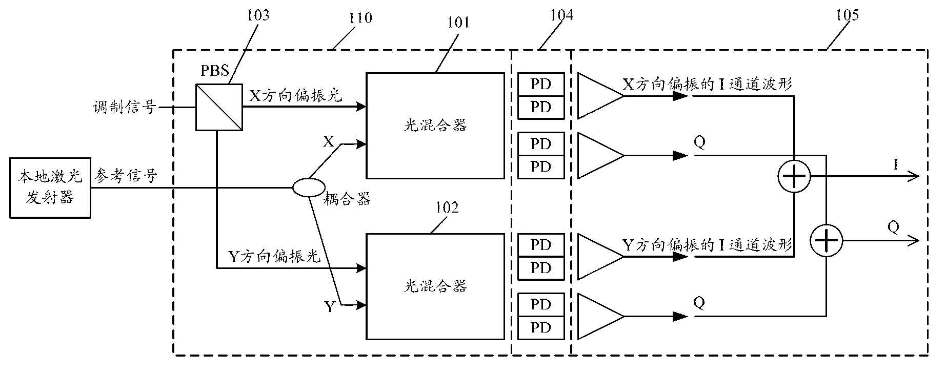
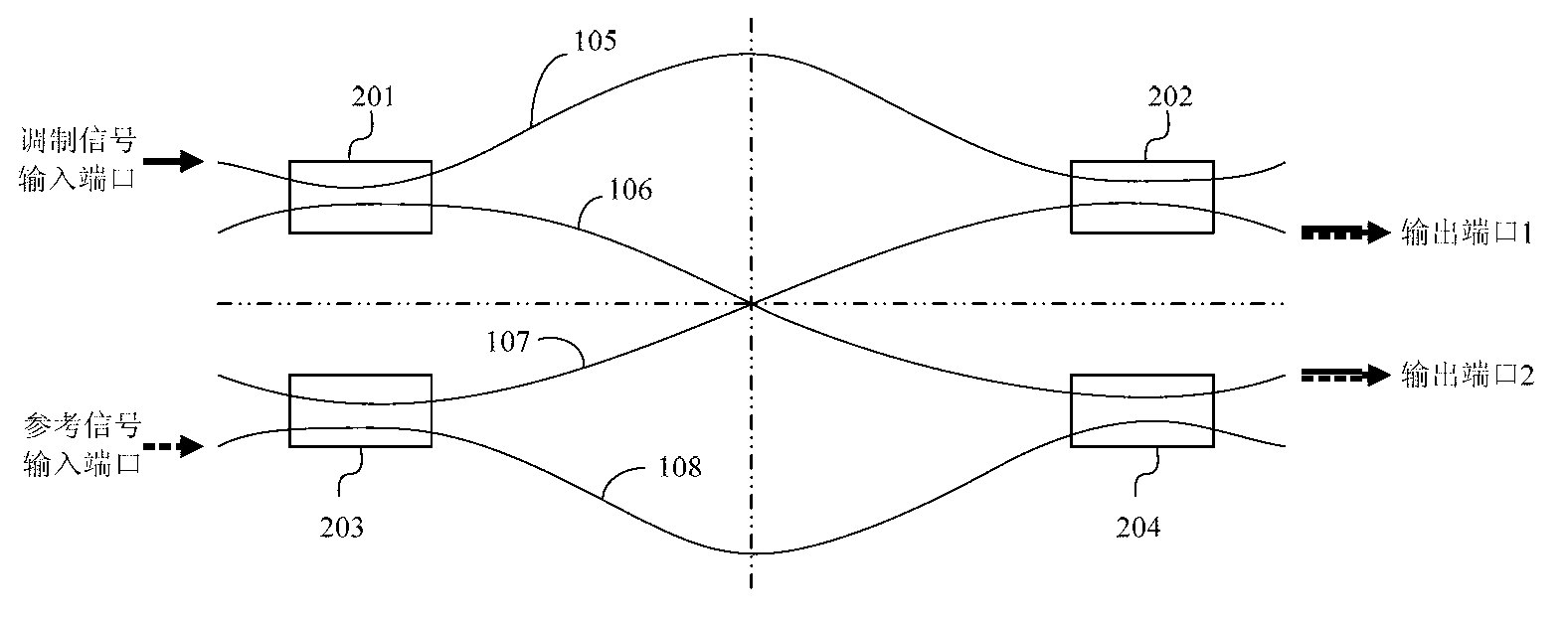
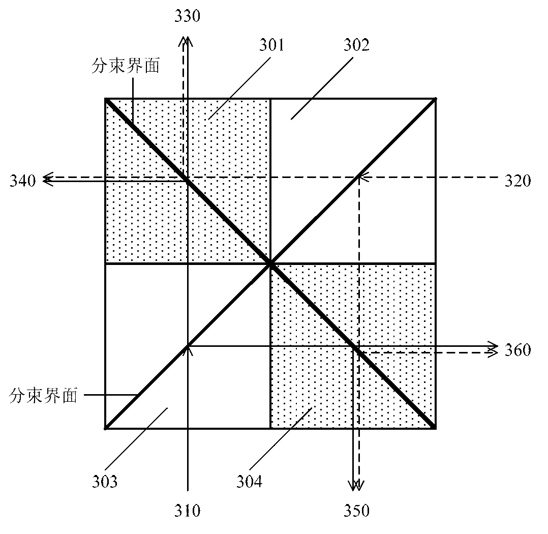
[0047] The inventors of the present invention consider that the non-polarizing beam splitter BS of the cube and the polarizing beam splitter PBS of the cube based on spatial optics can be realized by adopting lower cost, lower insertion loss and higher temperature stability Optical mixer for DP-QPSK optical signal demodulation. The BS is made of two right-angle prisms bonded together, and the bonding surface of the two right-angle prisms is coated with a beam-spl...


PUM


Abstract

The invention discloses an optical mixer and a method for demodulating a signal through the optical mixer. The optical mixer comprises two cubic unpolarized beam splitters (BS) and two cubic polarized beam splitters (PBS), wherein a cuboid block is formed by the two BSs and the two PBSs, the beam splitting interfaces of the two BSs are located in a first plane, the beam splitting interfaces of the two PBSs are located in a second plane, and the first plane is perpendicular to the second plane. According to the embodiment, the planar optical waveguide PLC technology is not used in the optical mixer, demodulation to the modulated signal is achieved through the two cubic unpolarized BSs and the two cubic PBSs, and the BSs and the PBSs are lower in cost, smaller in insertion loss, higher in temperature stability and based on space optics. Therefore, the cost of the optical mixer is reduced, the insertion losses of the optical mixer are reduced, and the temperature stability of the optical mixer is improved.

Description

technical field [0001] The invention relates to the field of optical fiber communication, in particular to an optical mixer and a signal demodulation method using the optical mixer. Background technique [0002] Optical fiber communication is a communication system that uses light waves as information carriers and transmits information through optical fibers. Because of its characteristics of large capacity, long transmission distance and fast transmission speed, it has been widely used in the field of high-speed optical communication. At present, in optical fiber communication networks, DP-QPSK (Dual Polarization Quadrature Phase Shift Keying, Dual Polarization Quadrature Phase Shift Keying) modulation technology based on coherent reception is generally used for demodulation and reception of 100Gpbs and higher-speed optical signals. This technology is applied to the coherent optical receiver in the optical fiber communication network to realize the demodulation and recepti...

Claims


Application Information

Patent Timeline
IPC IPC(8): G02B6/27H04B10/25
Inventor 陈思乡
Owner HISENSE BROADBAND MULTIMEDIA TECH
Learn More