
Assembling and disassembling tool of electric power fault indicator

A technology for removing tools and power failures, applied in the direction of overhead lines/cable equipment, etc., can solve the problems of the double-hoop structure to realize the difficulty of inductive power acquisition, the difficulty of disassembling the indicator, and the difficulty of pulling the ring, etc., to enhance the connection stability and operation. The effect of humanization and improving efficiency

Active Publication Date: 2013-08-21
BEIJING SIFANG JIBAO AUTOMATION +1
View PDF6 Cites 4 Cited by
  • Summary
  • Abstract
  • Description
  • Claims
  • Application Information

AI Technical Summary

Problems solved by technology

The double hoop structure is rarely used in the new generation of digital fault indicators due to the difficulty in realizing induction power acquisition.
The pull ring structure generally has problems such as difficulty in disassembling the movable pin and introducing the pull ring, and damage to the pull ring, which makes it difficult or even impossible to disassemble the indicator.

Method used


Image

  • Assembling and disassembling tool of electric power fault indicator
  • Assembling and disassembling tool of electric power fault indicator
  • Assembling and disassembling tool of electric power fault indicator

Examples


Embodiment Construction

[0020] The technical solution of the present application will be further described in detail below in conjunction with the accompanying drawings.

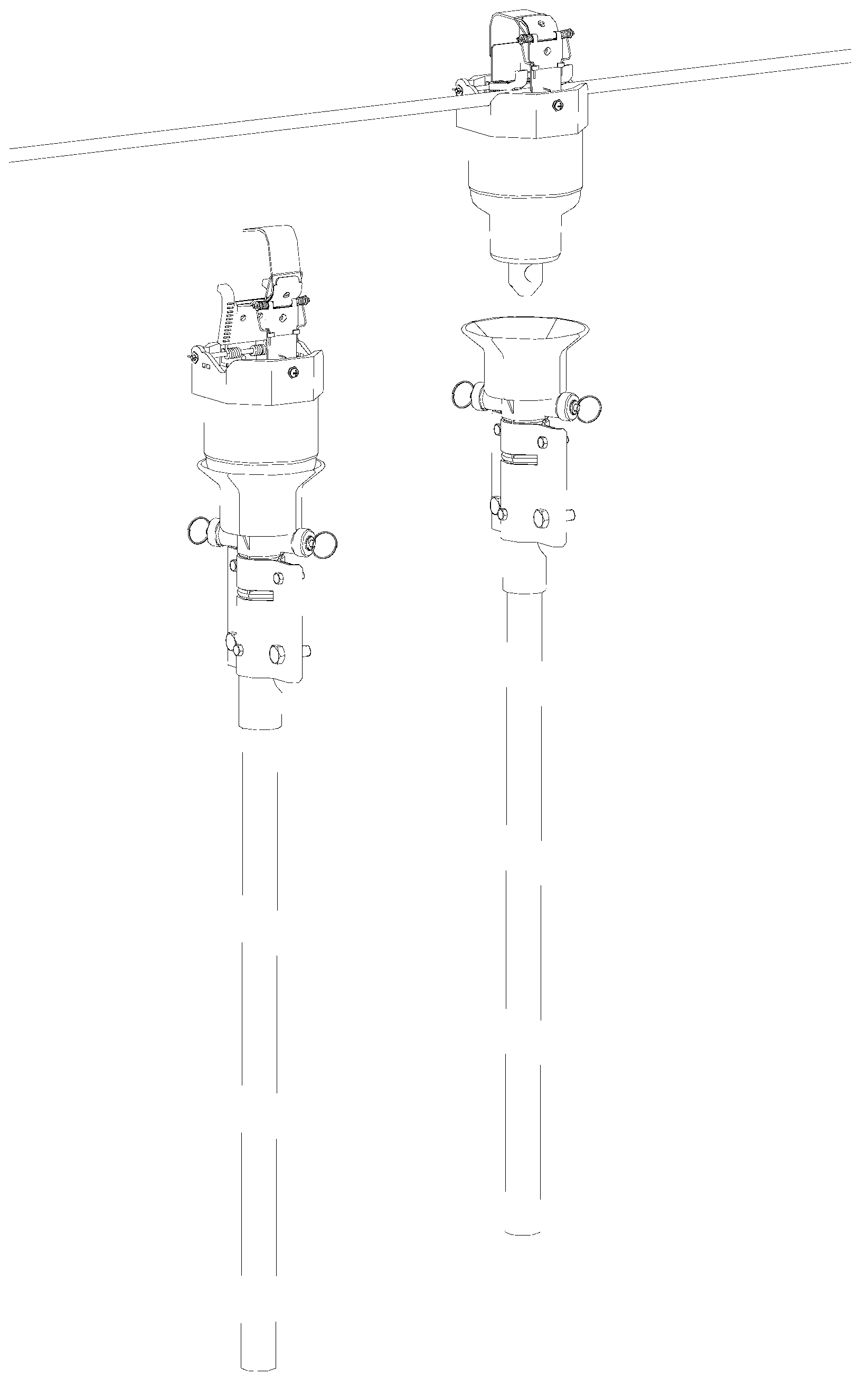
[0021] as attached figure 1 Shown is a schematic diagram of the structure of the power failure indicator when it is installed and disassembled. Among them, the left side is a schematic diagram of installing the power failure indicator on the power distribution line through the tool disclosed in this application when installing the power failure indicator, and the right side is the one that is disassembled by the tool when the power failure indicator needs to be removed from the distribution line. schematic diagram.

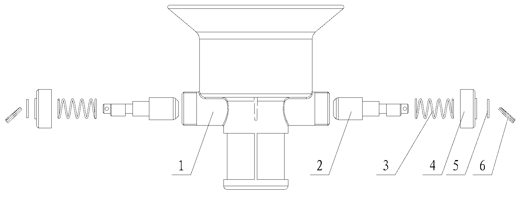
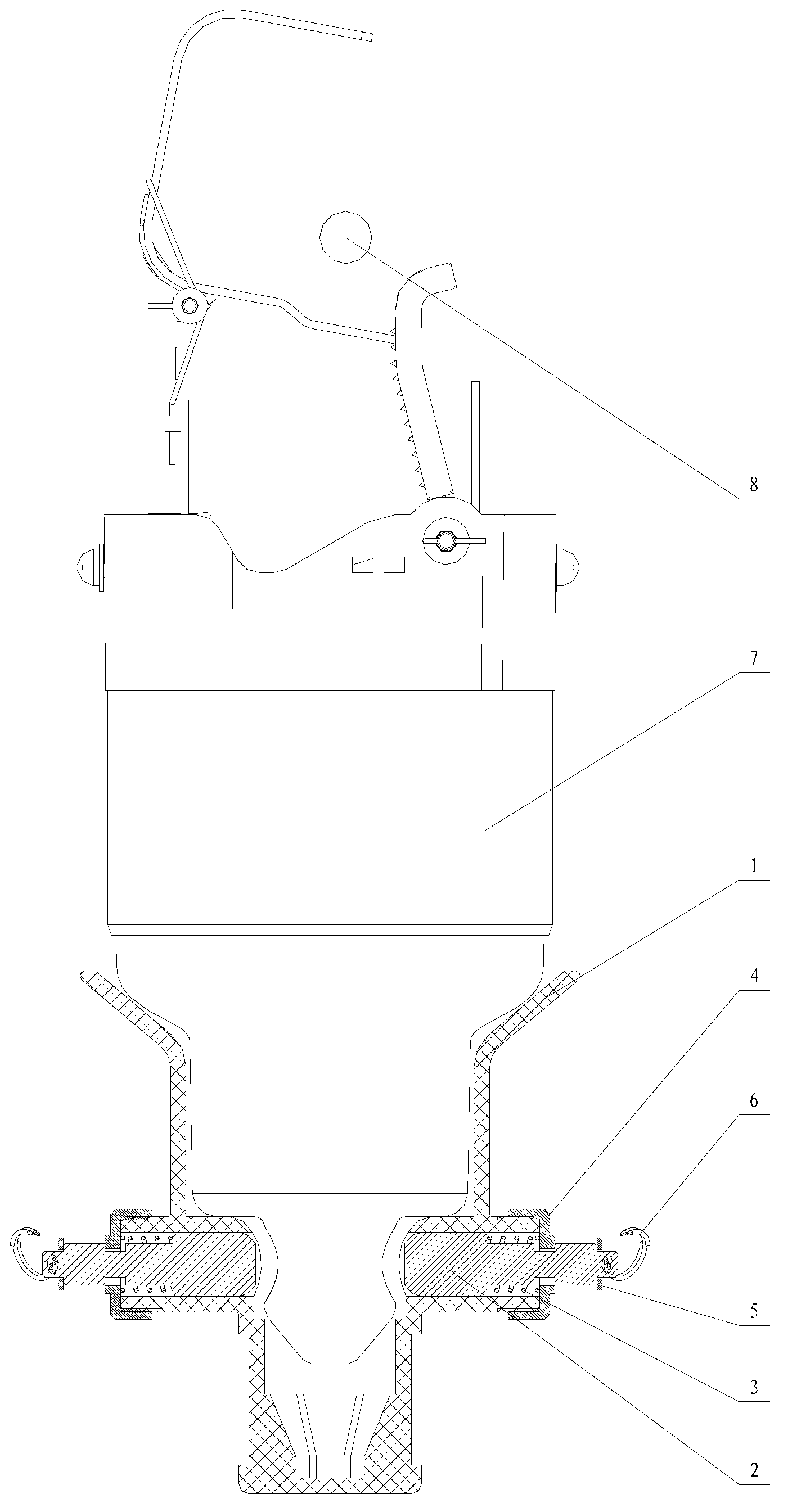
[0022] Such as figure 2 Shown is a schematic diagram of the disassembled structure of the power failure indicator installation and removal tool, the power failure indicator installation and removal tool includes a housing 1, a cylindrical pin 2, a cover 4, a spring 3, a gasket 5, and a pull ring 6,

[0023] The upp...


PUM


Abstract

The invention discloses an assembling and disassembling tool of an electric power fault indicator. The assembling and disassembling tool of the electric power fault indicator comprises a shell body, cylindrical pins, covers and springs. The upper portion of the shell body is of a hollow cylinder structure with a horn-shaped opening, and the lower portion of the shell body is provided with a cylindrical groove, wherein the diameter of the cross section of the cylindrical groove is smaller than the diameter of the cross section of the upper portion. The left side and the right side at the upper end of the cylindrical groove at the lower portion of the shell body are respectively provided with a cylinder pipeline. An open pore formed in the cylindrical groove is formed at one end of each cylinder pipeline, and a cover with an opening is arranged at the other end of each cylinder pipeline. The cylindrical pins are in the shape of a step-shaped cylinder, and are arranged in the cylinder pipelines arranged at the left side and the right side respectively. One end, with the largest diameter, of each cylindrical pin is capable of penetrating through the open pore formed in the cylindrical groove, and the other end of each cylindrical pin penetrates through the opening of each cover. A spring is arranged between one end, with the largest diameter, of each cylindrical pin and each cover. Opening grooves are formed in the cylindrical pins to be matched with the covers to carry out clamping and fixing. Assembling operation and disassembling operation can be carried out on the fault indicator conveniently, and the assembling and disassembling tool of the electric power fault indicator has the advantages of being convenient to assemble and use, balanced in stress, good in stability, attractive in appearance and the like.

Description

technical field [0001] The invention is a new type of tool structure for installing and dismounting a power failure indicator, which is suitable for installing and dismounting a matching type of power failure indicator on a power distribution line. Background technique [0002] The power fault indicator is installed on the distribution line and is mainly used to indicate faults such as short circuit and grounding of the distribution line. Since the installation and disassembly of the fault indicator is an outdoor pole operation, and the quantity is huge (it needs to be installed every 2-3 kilometers, or where there is a branch line), the quickness and reliability of the installation and disassembly of the fault indicator are of great importance to construction, It is very important for maintenance and other work. At present, the installation and disassembly tools of the power failure indicator are mainly for the disassembly of the double hoop clamp structure and the pull ri...

Claims


Application Information

Patent Timeline
IPC IPC(8): H02G1/02
Inventor 韩造林高锐陈俊李相焕
Owner BEIJING SIFANG JIBAO AUTOMATION
Learn More