Digital front end system used for power line carrier communication and implementation method of digital front end system

A power line carrier and digital front-end technology, applied in the application of power line communication, distribution line transmission system, wired transmission system, etc., can solve problems that have not been raised, and achieve reduction of interference, suppression of out-of-band interference, and reduction of out-of-band energy Effect

Active Publication Date: 2013-08-21
STATE GRID CORP OF CHINA +2
View PDF3 Cites 17 Cited by
  • Summary
  • Abstract
  • Description
  • Claims
  • Application Information

AI Technical Summary

Problems solved by technology

The method of Nyquist window function has been used in the receiving end processing of wireless communication OFDM system, but it has not been proposed in the power line carrier communication system

Method used


Image

  • Digital front end system used for power line carrier communication and implementation method of digital front end system
  • Digital front end system used for power line carrier communication and implementation method of digital front end system
  • Digital front end system used for power line carrier communication and implementation method of digital front end system

Examples


Embodiment 1

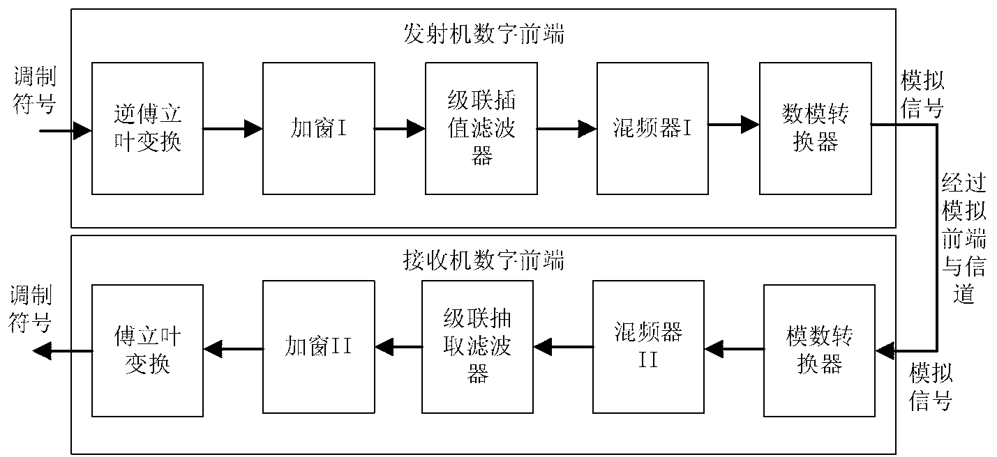
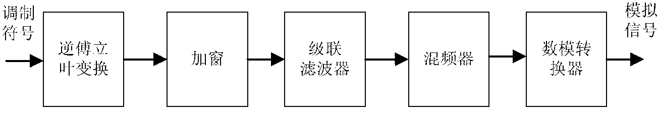
[0050] The structural example diagram of the transmitter in the digital front-end system provided by the present invention is as follows image 3 As shown, the center frequency can be selected between 0 Hz and 25 MHz, and the bandwidth supports flexible configuration between 7.8 kHz and 10 MHz.

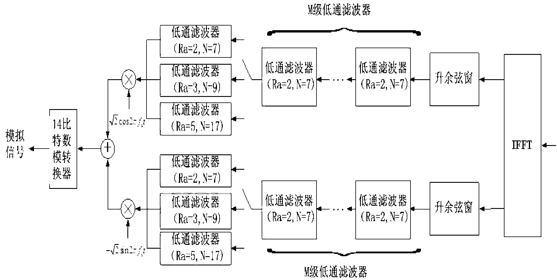
[0051] In this implementation, the digital front-end structure of the transmitter includes an inverse Fourier transform (IFFT) module, a raised cosine window windowing module, an interpolation low-pass filter with a rate conversion factor of 2, a rate conversion factor of 3 An interpolation low-pass filter, an interpolation low-pass filter with a rate conversion factor of 5, and a frequency point of f c mixer and a digital-to-analog converter (DAC). Using the 4096-point inverse Fourier transform module, the modulation symbols are respectively mapped to subcarriers 1 to 410 and subcarriers 3687 to 4096, and converted to an equivalent complex baseband signal in the time domain through ...

Embodiment 2

[0054] The structural example diagram of the receiver in the digital front-end system provided by the present invention is as Figure 5 As shown, in this implementation, the digital front-end structure of the receiver includes a Fourier transform (FFT) module, a raised cosine window windowing module, a decimation low-pass filter with a rate conversion factor of 2, a rate conversion factor A decimation low-pass filter of 3, a decimation low-pass filter with a rate conversion factor of 5, and a frequency point of f c mixer and an analog-to-digital converter (ADC). Such as Figure 5 As shown, the receiver performs the inverse operation corresponding to the transmitter. First, the input signal (analog signal) at the receiving end is converted into a digital bandpass signal by an analog-to-digital converter, and then downshifted by a mixer to become an equivalent complex baseband signal. Then, the equivalent complex baseband signal is converted to R by a first-order rate convers...

Embodiment 3

[0057] Transmitter and receiver raised cosine window schematic diagrams provided by the present invention are as Figure 6 as shown, Figure 6 A working mode of the raised cosine window in the transmitter and receiver is given, wherein the upper window is the raised cosine window at the transmitting end, and the lower window is the raised cosine window at the receiving end. The transmitter generates a Figure 6 Complete Orthogonal Frequency Division Multiplexing (OFDM) with cyclic prefix and cyclic suffix shown, symbol. The raised cosine window of the receiver can utilize N 5 cyclic prefix of sampling points, N 5 cyclic suffix of sampling points and 2N in OFDM symbols 5 sampling points to improve demodulation performance, N 5 dot cyclic prefix and N 5 The cyclic suffix of the dot must be guaranteed not to be affected by inter-symbol interference. In addition, N 1 The cyclic prefix and cyclic suffix of sampling points are used for the raised cosine window at the transmi...


PUM


Abstract

The invention relates to the field of electric power telecommunication used for supporting smart power grids, in particular to a digital front end system used for power line carrier communication and an implementation method of the digital front end system. The digital front end system comprises a transmitter and a receiver, wherein the transmitter and the receiver carry out communication in sequence. The transmitter comprises an inversion Fourier transformation module, a windowing module I, an interpolation filter, a frequency mixer I and a digital-analog converter, wherein the inversion Fourier transformation module, the windowing module I, the interpolation filter, the frequency mixer I and the digital-analog converter carry out communication in sequence. The receiver comprises an analog-digital converter, a frequency mixer II, an interpolation filter, a windowing module II and a Fourier transformation module, wherein the analog-digital converter, the frequency mixer II, the interpolation filter, the windowing module II and the Fourier transformation module carry out communication in sequence. The implementation method of the digital front end system comprises the following steps: 1, a modulation symbol is input to the transmitter and converted into an analog signal; 2, the analog signal is input to the receiver and converted into the modulation symbol. The digital front end system used for the power line carrier communication and the implementation method of the digital front end system combine a digital front end in the form of an equivalent complex number base band with a Nyquist windowing method, and have the advantages of supporting frequency band selection and bandwidth configuration, suppressing out-of-band interference, reducing sending signal out-of-band energy, and suppressing in-band narrow-band interference.

Description

technical field [0001] The invention relates to the field of power communication supporting smart grids, in particular to a digital front-end system supporting equivalent complex baseband OFDM modulation for power line carrier communication and an implementation method thereof. Background technique [0002] Compared with other communication systems, the power line carrier communication channel is more complex and changeable. The power line carrier communication channel has frequency selectivity, time variation, colored background noise, narrow-band interference and various impulse noises. These characteristics are mainly caused by various electrical appliances connected to the power line. For example, the European CE (Conformite EUROPEENNE) certification only measures the electromagnetic compatibility (EMC) characteristics of test appliances above 150 kHz, so the noise below 150 kHz is very high. At the same time, the attenuation that varies with transmission distance, grid...

Claims


Application Information

Patent Timeline
Patent Type & Authority Applications(China)
IPC IPC(8): H04L27/26H04B3/54
CPCH04B3/542H04B2203/5433
Inventor 高鸿坚布米勒·歌德刘伟麟杨冰李建岐
Owner STATE GRID CORP OF CHINA
Why Eureka
Try Eureka