A digital front-end system for power line carrier communication and its implementation method
A technology of power line carrier and digital front end, which is applied in the application of power line communication, distribution line transmission system, wired transmission system, etc., can solve problems that have not been raised, reduce interference, reduce out-of-band energy, and suppress out-of-band interference Effect
- Summary
- Abstract
- Description
- Claims
- Application Information
AI Technical Summary
Problems solved by technology
Method used
Image
Examples
Embodiment 1
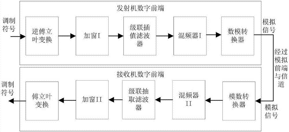
[0050] The structural example diagram of the transmitter in the digital front-end system provided by the present invention is as follows image 3 As shown, the center frequency can be selected between 0 Hz and 25 MHz, and the bandwidth supports flexible configuration between 7.8 kHz and 10 MHz.
[0051] In this implementation, the digital front-end structure of the transmitter includes an inverse Fourier transform (IFFT) module, a raised cosine window windowing module, an interpolation low-pass filter with a rate conversion factor of 2, a rate conversion factor of 3 An interpolation low-pass filter, an interpolation low-pass filter with a rate conversion factor of 5, and a frequency point of f c mixer and a digital-to-analog converter (DAC). Using the 4096-point inverse Fourier transform module, the modulation symbols are respectively mapped to subcarriers 1 to 410 and subcarriers 3687 to 4096, and converted to an equivalent complex baseband signal in the time domain through ...
Embodiment 2
[0054] The structural example diagram of the receiver in the digital front-end system provided by the present invention is as Figure 5 As shown, in this implementation, the digital front-end structure of the receiver includes a Fourier transform (FFT) module, a raised cosine window windowing module, a decimation low-pass filter with a rate conversion factor of 2, a rate conversion factor A decimation low-pass filter of 3, a decimation low-pass filter with a rate conversion factor of 5, and a frequency point of f c mixer and an analog-to-digital converter (ADC). Such as Figure 5 As shown, the receiver performs the inverse operation corresponding to the transmitter. First, the input signal (analog signal) at the receiving end is converted into a digital bandpass signal by an analog-to-digital converter, and then downshifted by a mixer to become an equivalent complex baseband signal. Then, the equivalent complex baseband signal is converted to R by a first-order rate convers...
Embodiment 3
[0057] Transmitter and receiver raised cosine window schematic diagrams provided by the present invention are as Figure 6 as shown, Figure 6 A working mode of the raised cosine window in the transmitter and receiver is given, wherein the upper window is the raised cosine window at the transmitting end, and the lower window is the raised cosine window at the receiving end. The transmitter generates a Figure 6 Complete Orthogonal Frequency Division Multiplexing (OFDM) with cyclic prefix and cyclic suffix shown, symbol. The raised cosine window of the receiver can utilize N 5 cyclic prefix of sampling points, N 5 cyclic suffix of sampling points and 2N in OFDM symbols 5 sampling points to improve demodulation performance, N 5 cyclic prefix of points and N 5 The cyclic suffix of the dot must be guaranteed not to be affected by inter-symbol interference. In addition, N 1 The cyclic prefix and cyclic suffix of sampling points are used for the raised cosine window at the t...
PUM
 Abstract
Description
Claims
Application Information
 - R&D
- Intellectual Property
- Life Sciences
- Materials
- Tech Scout
- Unparalleled Data Quality
- Higher Quality Content
- 60% Fewer Hallucinations
Browse by: Latest US Patents, China's latest patents, Technical Efficacy Thesaurus, Application Domain, Technology Topic, Popular Technical Reports.
© 2025 PatSnap. All rights reserved.Legal|Privacy policy|Modern Slavery Act Transparency Statement|Sitemap|About US| Contact US: help@patsnap.com


