Raw gas collection system

A collection system, original technology, applied to reduce gas emissions, furnaces, lighting and heating equipment, etc., can solve problems such as increased size and energy consumption of installations

Active Publication Date: 2013-08-21
GENERAL ELECTRIC TECH GMBH
View PDF11 Cites 4 Cited by
  • Summary
  • Abstract
  • Description
  • Claims
  • Application Information

AI Technical Summary

Benefits of technology

This technology improves how different fluids (such as molten metal) travel within an industrial process without causing issues such as uneven temperature distribution across various parts of it's equipment. By utilizing this technique, there will also reduce wasteful use of fuel during production while still producing high quality products with consistently good results over time.

Problems solved by technology

Technological Problem: In this patented method described in previous methods, there was always some energy waste when trying to remove impurities like iron oxide (FeO) particles during an electric arc furnace operation.

Method used


Image

  • Raw gas collection system
  • Raw gas collection system
  • Raw gas collection system

Examples


Embodiment Construction

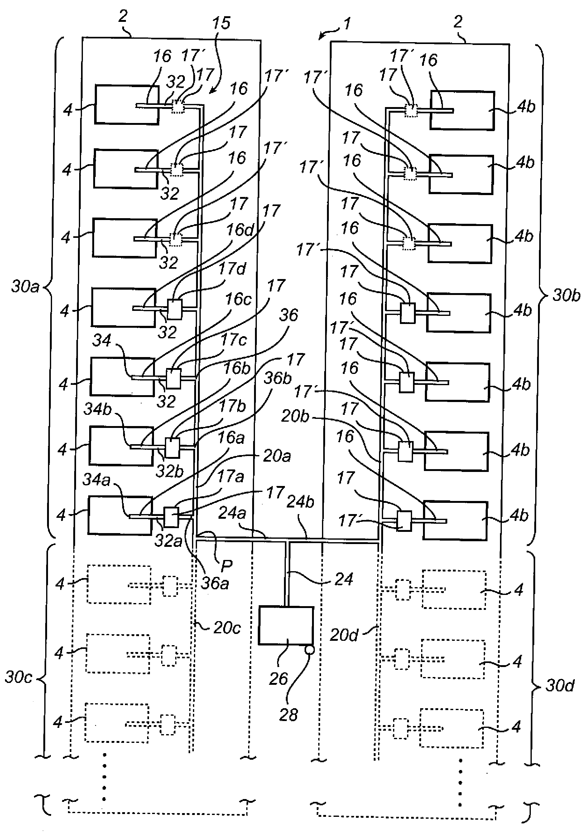
[0024] figure 1 is a schematic side view of the aluminum production facility 1 . The aluminum production plant 1 has an aluminum production cell chamber 2 in which a plurality of aluminum production cells or melting tanks 4 can be arranged. exist figure 1 In , only one smelting tank 4 is depicted for clarity and simplicity, and it will be understood that the electrolytic cell chamber 2 may typically include 50 to 200 smelting tanks 4 . The melting tank 4 includes a plurality of anode electrodes 6 , typically six to thirty anode electrodes, which are typically arranged in two parallel rows extending along the length of the melting tank 4 and into the contents 7 of the bath 8 . One or more cathode electrodes 10 are also located within bath 8 . The process carried out in the smelting tank 4 may be the well-known Hall-Elu process, in which alumina dissolved in a melt of fluorine-containing minerals is electrolyzed to form aluminum, and the smelting tank 4 thus acts as an electr...


PUM


Abstract

A raw gas collection system (15) for collecting raw gas from a plurality of aluminium smelting pots (4) is equipped with a plurality of branch ducts (16, 16a-d). Each branch duct (16, 16a-d) is arranged to channel a respective branch flow (32, 32a-b) of raw gas from an aluminium smelting pot (4) to a collecting duct (20a), which is common to and shared by branch ducts (16, 16a-d). Several of the branch ducts (16, 16a-d) are equipped with a combined heat transfer and flow resistance generating element (17) to remove heat from the respective branch flow (32, 32a-b) of raw gas and to balance the flow of raw gas in the raw gas collecting system (15). The combined heat transfer and flow resistance generating elements (17) reduce the need for adjusting the respective branch duct (16, 16a-d) flow volumes using dampers, thereby reducing the power required to transport the raw gas through the system.

Description


Claims


Application Information

Patent Timeline
Owner GENERAL ELECTRIC TECH GMBH
Why Eureka
Try Eureka