
Bonding device

A welding device and welding point technology, applied in welding equipment, auxiliary devices, manufacturing tools, etc., can solve the problems of increasing proportion and difficulty in shortening welding time, and achieve the effect of increasing production quantity

Active Publication Date: 2013-08-21
KAIJOO KK
View PDF5 Cites 3 Cited by
  • Summary
  • Abstract
  • Description
  • Claims
  • Application Information

AI Technical Summary

Problems solved by technology

[0022] If the distance from the search height to the welding point becomes longer or the position detection by the position detection unit lags, the time will increase, and the proportion of such time lag and time increase to the entire welding time will increase. It will become difficult to shorten the welding time

Method used

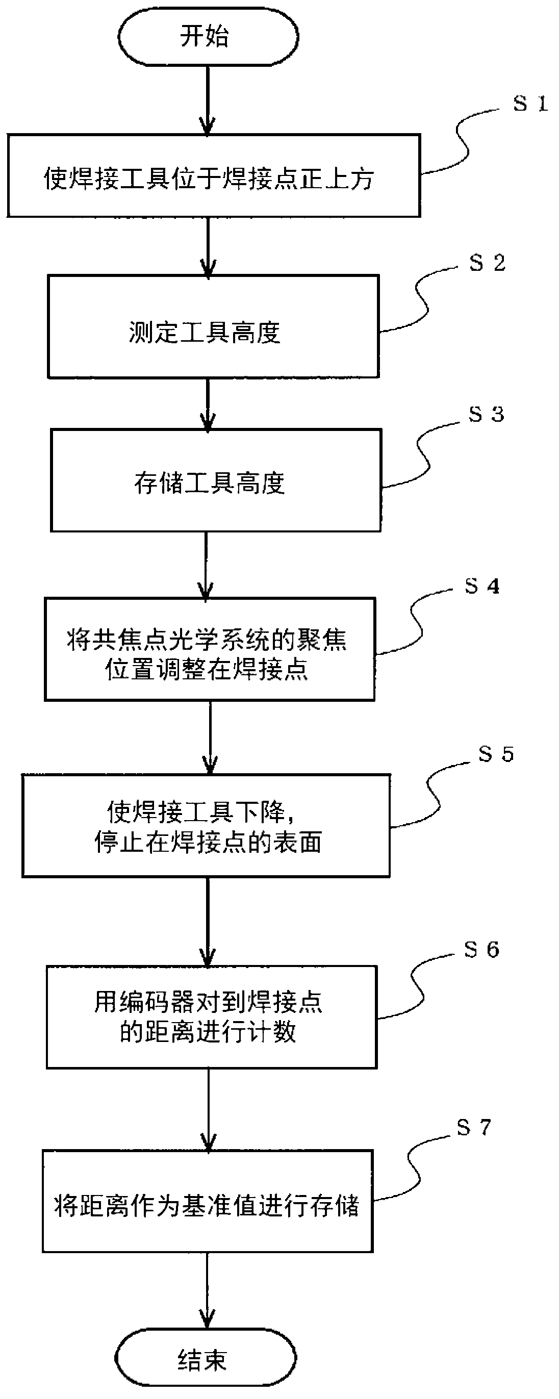
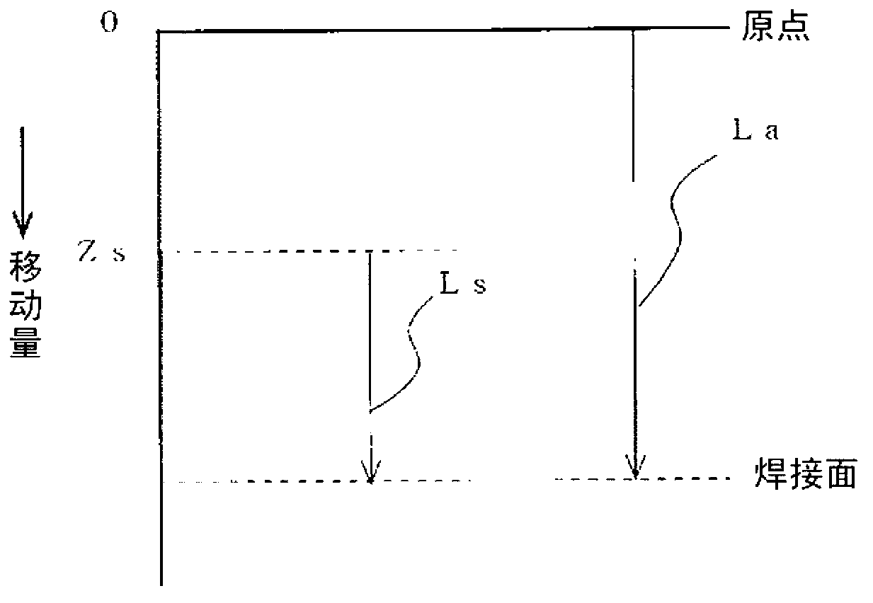

Image

  • Bonding device
  • Bonding device
  • Bonding device

Examples


Embodiment Construction

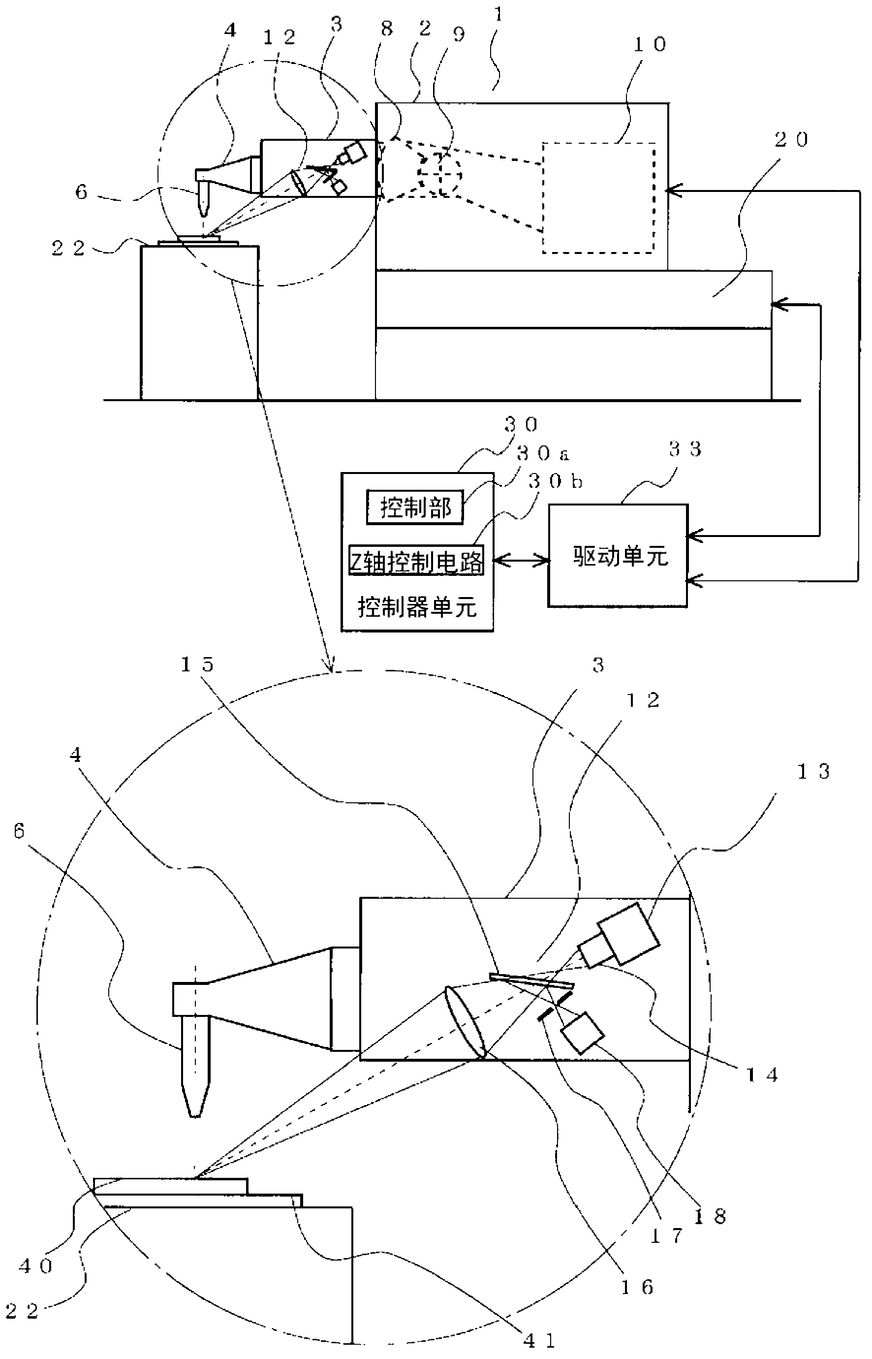
[0052] Hereinafter, embodiments of the welding device according to the present invention will be described with reference to the drawings. In addition, as the bonding device, a wire bonding device for connecting a pad as a first bonding point and a lead as a second bonding point with a gold wire or the like will be described.

[0053] [Structure of Welding Device]

[0054] figure 1 It is a figure including a partial enlarged view showing the structure of the welding apparatus of the present invention. Additionally, for Figure 7 The same components as those of the conventional wire welding apparatus shown are denoted by the same reference numerals, and a detailed description of the structure is omitted.

[0055] like figure 1 As shown, the wire welding device 1 includes: a welding head 2; an XY stage 20 that carries the welding head 2 and can move in the two-dimensional direction of the XY axis; A welding platform 22 of the frame; and a controller unit 30 for controlling...


PUM


Abstract

The purpose of the invention is to provide a bonding device that is capable of bonding at high speed without measurement of a bonding point height before a search operation or before bonding. The invention comprises: a confocal point optical system mounted on a bonding arm capable of swinging in the up / down direction and detecting the focused focal point of a bonding point positioned on a surface of a part to be bonded; a bonding tool that bonds and is integrally mobile with the bonding arm; and a position detection means that detects the position of the bonding tool. Control is provided so that the bonding tool descends a specified distance (focused focal point reference descent amount), from a bonding tool position the position detection means detected during the descent of the bonding tool, said bonding tool position being detected by means of focused focal point detection by the confocal point optical system, to a preset bonding point, and stops on the bonding point.

Description

technical field [0001] The present invention relates to the use of a wire to connect a first bonding point (such as an electrode (pad) on a semiconductor chip (IC chip) as a component to be bonded) to a second bonding point (such as a The welding device for connecting the external lead on the lead frame of the frame), especially a welding device capable of high-speed welding. Background technique [0002] In the past, for the soldering device that connects the bonding pad on IC chip and external lead, known such as Figure 7 The wire welding setup shown. [0003] Figure 7 It is a figure which shows the structure of the conventional wire welding apparatus, Figure 8 It is a figure showing the tool height and the search height (サーチレベル) in the conventional wire welding device, in Figure 9 Among them, (a) is a diagram showing the velocity waveform when the welding tool (capillary) of the conventional wire bonding device is lowered, and (b) is a diagram showing the trajectory...

Claims


Application Information

Patent Timeline
Patent Type & Authority Applications(China)
IPC IPC(8): H01L21/60
CPCH01L24/78H01L2924/00014H01L2224/78301H01L2224/78753H01L24/85H01L2224/859H01L2224/451H01L2224/45144H01L2924/12042H01L2224/85205H01L2224/05599H01L2224/85399H01L2224/48H01L2924/00H01L2924/00015H01L2224/45015H01L2924/207B23K3/08
Inventor 杉藤哲郎
Owner KAIJOO KK
Learn More