A bending part control mechanism and endoscope equipment thereof

A control mechanism and bending part technology, applied in the field of endoscopy, can solve the problems of complex assembly of the control mechanism, achieve the effects of simplifying the transfer and adjustment process, flexible assembly, and saving the trouble of controlling the wire rope

Active Publication Date: 2015-09-23
SONOSCAPE MEDICAL CORP
View PDF6 Cites 0 Cited by
  • Summary
  • Abstract
  • Description
  • Claims
  • Application Information

AI Technical Summary

Problems solved by technology

[0005] The embodiment of the present invention provides a bending part control mechanism to solve the problem of complex assembly of the control mechanism in the prior art

Method used


Image

  • A bending part control mechanism and endoscope equipment thereof
  • A bending part control mechanism and endoscope equipment thereof
  • A bending part control mechanism and endoscope equipment thereof

Examples


Embodiment 1

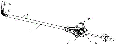
[0032] like image 3 As shown, an ultrasonic probe laparoscope 1 generally includes a bending part control mechanism 2 , a rigid insertion tube 4 inserted into the abdominal cavity, a bending part 5 that can bend in multiple directions, and an ultrasonic sensor 6 . When working, the ultrasonic probe laparoscope 1 is connected to the ultrasonic host through a cable, and the rigid insertion tube 4, the bending part 5, and the ultrasonic sensor 6 are inserted into the abdominal cavity of the human body, and the user controls the bending part 5 and the ultrasonic sensor 6 through the bending part control mechanism 2 Swing to adjust the ultrasound imaging scan angle and position.

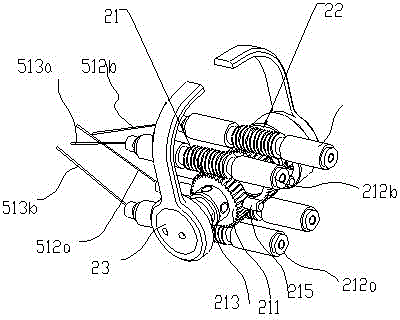
[0033] like figure 1 , 2 As shown, the bending part 5 includes a curved snake pipe and a snake pipe joint flange; the curved snake pipe includes a number of snake pipe joints and steel wire ropes (512a, 512b) and (513a, not shown in the figure) for connecting the snake pipe joints in series ). One en...

Embodiment 2

[0047] The embodiment of the present invention also discloses a device with the bending part control mechanism as described in the first embodiment. The device may be an endoscope device. The structure of the bending part control mechanism is as described in the first embodiment. This will not be repeated here.


PUM


Abstract

The invention provides a bending section control mechanism which is used for controlling movement of a steel wire rope of a bending section so as to control bend of the whole bending section. The bending section control mechanism comprises worm and gear components, a control handle and an outer shell, each worm and gear component comprises a worm wheel and two worms, the two worms are symmetrically arranged on two sides of the worm wheel, and the worms on two sides are driven by rotation of the worm wheel to move in a straight line in opposite directions. The control handle is connected with the worm wheel and drives the worm wheel to rotate, and the outer shell covers the worm and gear components. The control handle is arranged outside the outer shell, so that workers can operate the control handle conveniently. The invention further provides a corresponding device. Through the adoption of the technical scheme, the complex assembling problem of the control mechanism in the prior art is solved.

Description

technical field [0001] The invention relates to the field of endoscopes, in particular to a bending part control mechanism and endoscope equipment. Background technique [0002] Existing laparoscopic ultrasound probes generally include four parts: an operating handle, an insertion hard tube, a curved tube, and an end sensor. A flexible steel wire rope is connected between the curved tube and the operating handle. By rotating the handle, the steel wire rope is pulled for telescopic movement, and the curved tube is controlled to bend in two mutually orthogonal planes to realize the deflection of the end sensor. Currently common laparoscopic probes have two rotating handles, and each rotating handle controls the bending of the bending tube in a plane, and the bending range is about + / -100°. [0003] The existing technical scheme: two steel wire ropes are arranged symmetrically, one end is fixed on the far end of the steel wire rope, and the other end is wound around the rope w...

Claims


Application Information

Patent Timeline
Patent Type & Authority Patents(China)
IPC IPC(8): A61B1/005A61B1/313A61B17/94
Inventor 邵敏周曙光陈雄孙强
Owner SONOSCAPE MEDICAL CORP
Why Eureka
Try Eureka