Multi-section bending radius numerical-control die-free bending shaping method and equipment

A technology of bending radius and forming equipment, which is applied in the direction of heat exchange equipment, etc., can solve the problem that the arc processing of multiple sections with different bending radii is difficult to realize, and achieve the effect of avoiding overturning and avoiding wear

Inactive Publication Date: 2013-08-28
无锡凯博易机电科技有限公司 +1
View PDF5 Cites 8 Cited by
  • Summary
  • Abstract
  • Description
  • Claims
  • Application Information

AI Technical Summary

Problems solved by technology

At the same time, the unique multi-section arc processing with different bending radii is difficult to r

Method used


Image

  • Multi-section bending radius numerical-control die-free bending shaping method and equipment
  • Multi-section bending radius numerical-control die-free bending shaping method and equipment
  • Multi-section bending radius numerical-control die-free bending shaping method and equipment

Examples


Embodiment 1

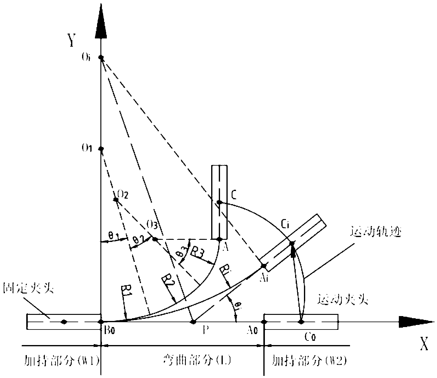
[0042] Such as figure 1 As shown, the principle diagram of the method of the present invention, in the figure: the workpiece is divided into three parts: the holding part W1, the bending part L, and the holding part W2. The holding part W1 is clamped with a fixed chuck, the holding part W2 is clamped with a moving chuck, and the bending part L is from the end B0 of the fixed chuck to the head A0 of the moving chuck. Point C is the midpoint of the moving chuck after bending. The center of the moving chuck moves from C0 to Ci, and then to point C. The radius of curvature Ri is the radius of curvature when the bending angle is θi. figure 1 Among them, O1, O2, and O3 are the centers of circles when the radii of curvature are R1, R2, and R3, respectively. figure 1Among them, O1, O2, and O3 are the centers of circles when the radii of curvature are R1, R2, and R3, respectively. Therefore, as long as the starting and ending positions of the workpiece bending are known, as well as...

Embodiment 2

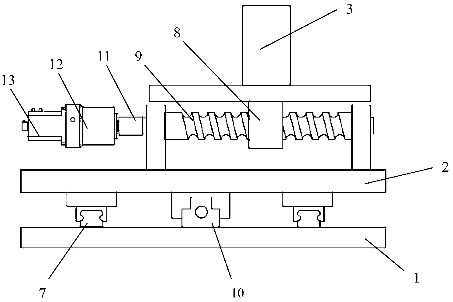
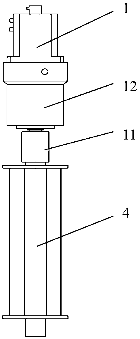
[0063] This embodiment provides a dieless bending and forming equipment, including a translation chuck and a rotation chuck, a driving device, a bending platform, and a numerical control system. Such as Figure 2-3 As shown in the figure: 1: base, 2: sliding platform, 3: translation chuck, 4: rotating chuck, 7: guide rail, 8: lead screw connection block, 9: lead screw, 10: lead screw support seat , 11: coupling, 12: reducer, 13: servo motor. Wherein: the base 1, the sliding platform 2, and the guide rail 7 constitute the bending platform; the lead screw connection block 8, the lead screw 9, the lead screw support seat 10, the shaft coupling 11, the reducer 12, and the servo motor 13 constitute the driving device.

[0064] The guide rail 7 is arranged on the base 1 and the sliding platform 2, the guide rail on the bottom plate 1 and the guide rail on the sliding platform are perpendicular to each other, and the translation chuck 3 is connected to the lead screw 9 on the slidin...

Embodiment 3

[0068] In another embodiment of the present invention, the used dieless bending forming equipment such as Figure 4 As shown, the difference from Example 2 is that two guide rails parallel to the Y direction are installed on the base 1 to support and guide the linear movement of the sliding platform 2 in the Y direction, and two guide rails parallel to the front are installed on the sliding platform 2. The guide rail is used to support and guide the linear movement of the translation chuck in the X direction. There is a sprocket with a small modulus in the reduction box 6, which drives the large sprocket below the rotating chuck 4 through the chain, thereby driving the rotating chuck 4.

[0069] Such as Figure 5 As shown, the working steps of this equipment are: clamp the workpiece after passing through the translational chuck 3, and then pass through the rotating chuck 4, control the speed of the servo motor according to the numerical control program, and then control the ba...


PUM


Abstract

The invention provides a multi-section bending radius numerical-control die-free bending shaping method and equipment. The equipment comprises a translational chuck, a rotating chuck, a driving device, a bending platform and a numerical control system, a clamping device is mounted on each of the translational chuck and the rotating chuck, the translational chuck is used for realizing horizontal motion of a workpiece in two orthogonal directions, the rotating chuck is used for realizing rotating angle motion of the workpiece, the driving device is used for driving the translational chuck and the rotating chuck which are mounted with the clamping devices to correspondingly move, the bending platform is used for fixing the translational chuck and the rotating chuck and also serves as a working platform for bending the workpiece, and the numerical control system determines a moving track program of the translational chuck and the rotating chuck according to the workpiece to be bent and controls the driving device according to the program to control the clamping devices to move according to set tracks. By the multi-section bending radius numerical-control die-free bending shaping method and the equipment, no bending die is needed when a heat exchanger is bent, and flexible bending of the workpiece is realized by controlling moving tracks of clamps clamping the workpiece; and die-free bending with multiple bending radiuses can be realized.

Description

technical field [0001] The invention relates to a specific technology of a dieless bending forming process, in particular to a numerically controlled dieless bending forming process suitable for heat exchangers, especially for bending workpieces with multiple sections of different bending radii. Background technique [0002] The bending and forming process of materials is widely used in the production process of social life, especially the bending and forming of heat exchangers is widely used in transportation, construction, electric power, air conditioning, petroleum, chemical industry, aviation, aerospace, and other industrial sectors. application. [0003] At present, the bending process of heat exchangers is mostly realized by means of die bending, and the radius of the bending die is the radius of the material to be bent. In order to realize this process, it is necessary to manufacture a high-precision bending die, and after a long period of use, the bending die will b...

Claims


Application Information

Patent Timeline
IPC IPC(8): B21D53/02B21D11/00
Inventor 张卿卿张志伟唐鼎李大永彭颖红韩维建
Owner 无锡凯博易机电科技有限公司
Why Eureka
Try Eureka