Scrap cutter

A chip and cutter technology, which is applied in the field of waste chip devices, can solve the problems of damage to the chip conveyor, and the waste chips cannot be cut off in time, so as to achieve the effects of convenient operation, convenient collection work, and safety assurance.

Inactive Publication Date: 2013-08-28
GUIZHOU UNIV
View PDF7 Cites 11 Cited by
  • Summary
  • Abstract
  • Description
  • Claims
  • Application Information

AI Technical Summary

Problems solved by technology

[0003] The technical problem to be solved by the present invention is to provide a chip cutter to solve the problem that the waste chips generated in the production process of machining cente

Method used


Image

  • Scrap cutter

Examples


Embodiment Construction

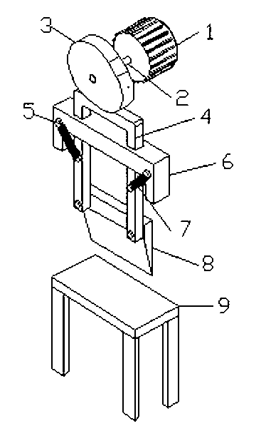
[0012] Such as figure 1 As shown, a chip cutter includes a motor 1, the motor 1 is connected with the cam 3 through the rotating shaft 2, the driven rod 4 is below the cam 3, and the driven rod 4 is a rectangular frame, and the rectangular frame includes two vertical sides and a Horizontal sides, and the cross-section of the rectangular shelf is rectangular. Two vertical limits of the rectangular frame are placed in the chute that has on the frame 6, and the horizontal limit contacts with the cam 3. Two back-moving springs 7 are arranged symmetrically at the two ends of the frame 6, and the two ends of the back-moving spring 7 are respectively connected on the frame 6 and the driven rod 4 by bolts 5, and the back-moving spring 7 and the two vertical sides of the rectangular frame have a angle. The lower end of the driven rod 4 is connected with a cutting knife 8, and below the cutting knife 8 is a chopping block 9.

[0013] The motor 1 is fixed on the upper end of the outle...


PUM


Abstract

The invention discloses a scrap cutter. The scrap cutter comprises a motor (1), wherein the motor (1) is connected with a cam (3) through a rotary shaft (2); a driven rod (4) is positioned below the cam (3) and is arranged in a sliding groove of a rack (6); reset springs (7) are arranged on the rack (6) and are connected with the driven rod (4); a cutting knife (8) is connected to the lower end of the driven rod (4); and a cutting board (9) is arranged below the cutting knife (8). According to the scrap cutter, the motor is used as a driver, and the cam (3) rotates to drive the driven rod (4) so as to further drive the cutting knife (8) to reciprocate vertically to cut scraps off. The scrap cutter is reasonable in structural design and high in efficiency, the problem that overlong scraps are taken into a scrap remover through an outlet of the scrap remover can be effectively solved, and the scrap remover is prevented from being damaged.

Description

technical field [0001] The invention relates to a device for processing waste chips generated during the processing of machining equipment such as a machining center, and belongs to the field of machining equipment. Background technique [0002] At present, machining centers, CNC lathes, milling machines, etc. on the market produce chips of different lengths, and the chips are usually conveyed from a low place to a high place with a chip conveyor. At the exit, the longer waste chips tend to roll back inside along the chain of the chip conveyor, causing the chip conveyor to be easily damaged. Therefore, it is necessary to design a chip cutter that can cooperate with the machining center equipment. Contents of the invention [0003] The technical problem to be solved by the present invention is to provide a chip cutter to solve the problem that the waste chips generated in the production process of machining centers such as machining centers cannot be cut off in time, preve...

Claims


Application Information

Patent Timeline
IPC IPC(8): B23Q11/00B23D27/00
Inventor 刘倩周兵兵黄放
Owner GUIZHOU UNIV
Why Eureka
Try Eureka