High-precision position detection device and method

A detection device and high-precision technology, applied in the field of optical detection, can solve the problems of increasing equipment size, increasing equipment cost, reducing equipment reliability, etc., and achieve the effect of high measurement accuracy and simple structure

Active Publication Date: 2013-08-28
LIAONING CROWNTECH PHOTONICS
View PDF6 Cites 5 Cited by
  • Summary
  • Abstract
  • Description
  • Claims
  • Application Information

AI Technical Summary

Problems solved by technology

[0004] In this kind of detection equipment, the moving range of the movable mirror is consistent with the maximum working distance of the optical system, so when the distance between the optical system is large, the moving and detection range of the movable mirror also needs to be expanded accordingly,

Method used


Image

  • High-precision position detection device and method
  • High-precision position detection device and method

Examples


Embodiment 1

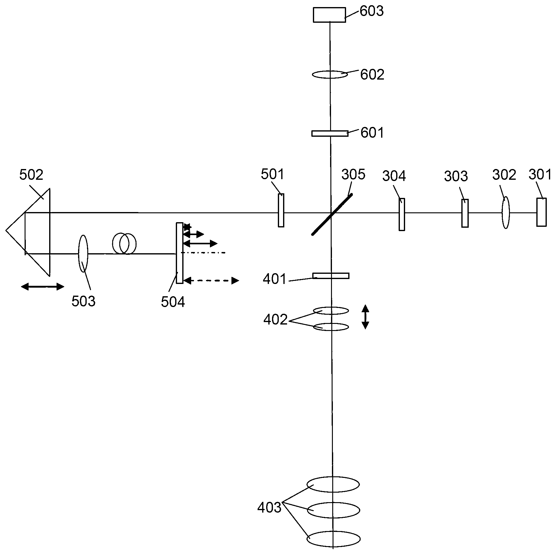
[0051] Such as figure 2 As shown in the structure diagram of the detection device of the present invention, the short coherent light source 301 passes through the collimator lens 302, becomes parallel light, passes through the polarizer 303 and the 1 / 2 wave plate 304, and enters the polarization beam splitter in a certain polarization direction 305, after passing through the beam splitter, a beam of light is transmitted, and after passing through the first 1 / 4 wave plate 501, it enters a movable total reflection mirror 502, and the light emitted from the total reflection mirror 502 passes through a coupling lens 503 to couple the light to In an end-reflection fiber optic beam splitter 504, the end-reflection fiber optic beam splitter 504 is a 1×n beam splitter, which divides one path of light into n paths of light, and there are different optical path differences between the n paths of light. The end of each fiber branch is coated with a reflective film, and the reflected lig...


PUM

PropertyMeasurementUnit
Coherence lengthaaaaaaaaaa

Abstract

The invention discloses a high-precision position detection device and a high-precision position detection method and belongs to the field of optical detection. The device comprises a short coherent light source, a collimating lens, a polarizer, a 1/2 wave plate, an optical splitter, a holophote a coupling lens, an end reflection fiber beam splitter, a focusing lens, a polarization analyzer, a sensor, two 1/4 wave plates and a multifocal lens; and the parts form a reference light path and a measurement light path. The optical path difference of different branches in the reference light path is fixed and different; and if assuming a test range is L and the reference light path comprises n branches, in order to test the optical surface space in the length of L, a movable lens is only required to move a distance of L/n, and the positions of different optical surfaces in the L range of a tested system can be accurately known by analyzing the position of the movable lens and the central position of interference fringe. The detection device has the advantages of wide detection range, small moving range of the movable lens, simple structure and high measuring accuracy.

Description

technical field [0001] The invention relates to the field of optical detection, in particular to a high-precision position detection device and method using light for detection. Background technique [0002] In a complex and high-precision optical system, it is necessary to test the distance between the assembled optical lenses. Since they have been assembled, they cannot be tested by mechanical means, and can only be checked in a non-contact way. A more suitable This application is carried out using the short coherent light source method, see the SPIE document "Contact-free on-axis metrology for the fabrication and testing of complex optical systems", the method given in this document uses Michelson's interferometer structure principle, through The method of moving the position of the movable lens in the reference arm to match the measured optical surface, and to test the position of different optical surfaces in the optical system. [0003] figure 1 The principle structu...

Claims


Application Information

Patent Timeline
IPC IPC(8): G01B11/00G01B11/14
Inventor 曹晓君白春伏碧德龚婧瑶
Owner LIAONING CROWNTECH PHOTONICS
Why Eureka
Try Eureka