
Fast antenna testing device and method based on hardware triggering

A test device and antenna technology, applied in the direction of the antenna radiation pattern, etc., to achieve the effects of short total test time, small communication delay, and short switching time

Active Publication Date: 2013-08-28
CHINA ELECTRONIS TECH INSTR CO LTD
View PDF5 Cites 28 Cited by
  • Summary
  • Abstract
  • Description
  • Claims
  • Application Information

AI Technical Summary

Problems solved by technology

[0009] The present invention proposes a fast antenna testing device based on hardware triggering, which solves the problem of coordinating and controlling the test turntable, measuring instruments, switch units and other components in the existing multi-probe antenna test and quickly completes the test

Method used


Image

  • Fast antenna testing device and method based on hardware triggering
  • Fast antenna testing device and method based on hardware triggering
  • Fast antenna testing device and method based on hardware triggering

Examples


Embodiment Construction

[0024]The following will clearly and completely describe the technical solutions in the embodiments of the present invention with reference to the accompanying drawings in the embodiments of the present invention. Obviously, the described embodiments are only some, not all, embodiments of the present invention. Based on the embodiments of the present invention, all other embodiments obtained by persons of ordinary skill in the art without creative efforts fall within the protection scope of the present invention.

[0025] In the existing multi-probe antenna test, how to coordinate and control the various components of the test system such as the test turntable, measuring instruments and switch units and quickly complete the test is an urgent problem to be solved. The invention discloses a fast antenna testing device and method based on hardware trigger. In the antenna testing system, the multi-probe electronic scanning antenna testing system is to improve the testing speed by a...


PUM


Abstract

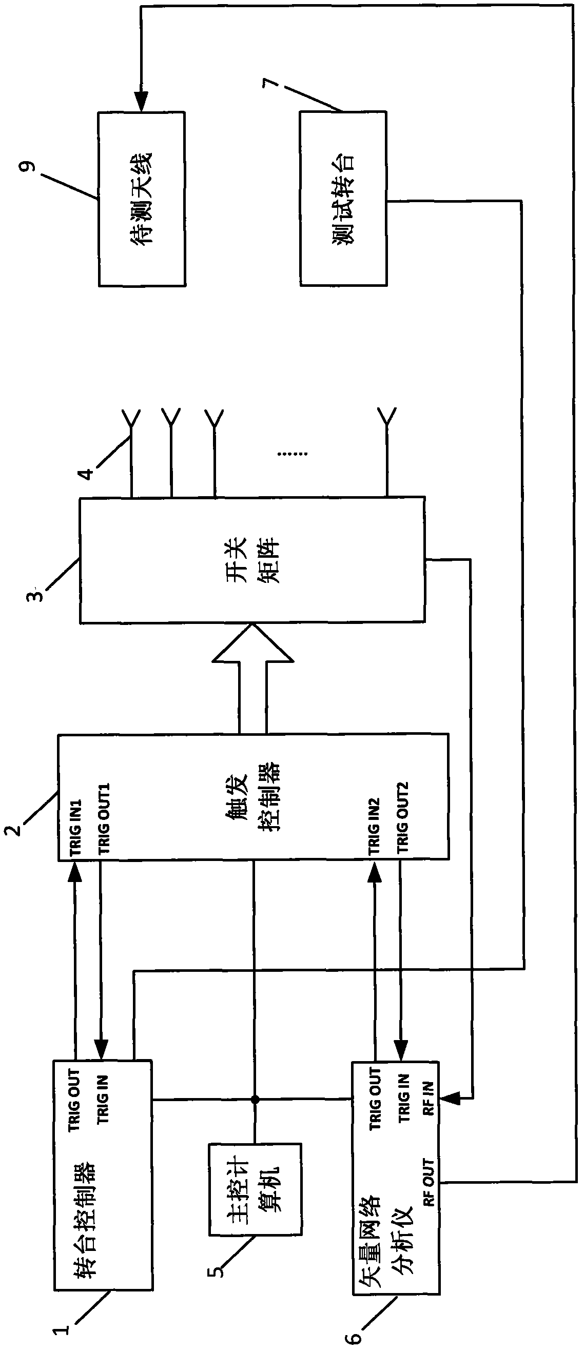
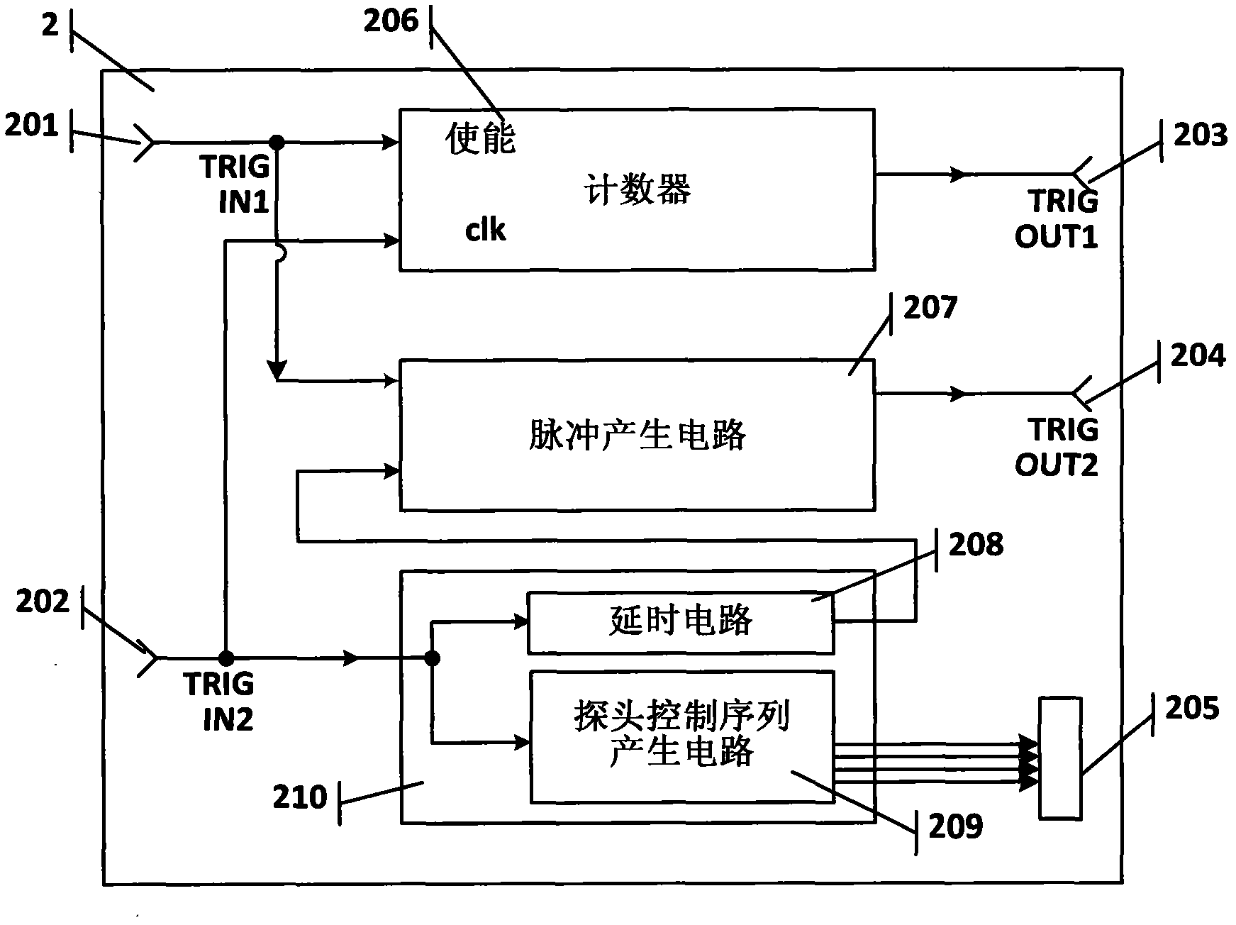
The invention discloses a fast antenna testing device and method based on hardware triggering. The device and method solves the problems of coordinated control of components such as a test turntable, a measurement instrument and a switch unit, and fast testing in a multi-probe antenna test in the prior art. The fast antenna testing device based on the hardware triggering comprises a main control computer, a vector network analyzer, a turntable controller, a triggering controller, a switch matrix, a receiving probe matrix, the test turntable and an antenna to be tested. By means of the fast antenna testing device and method based on the hardware triggering, communication delay is little, switching time of a switch is short, switching frequency is small, and total test time is short.

Description

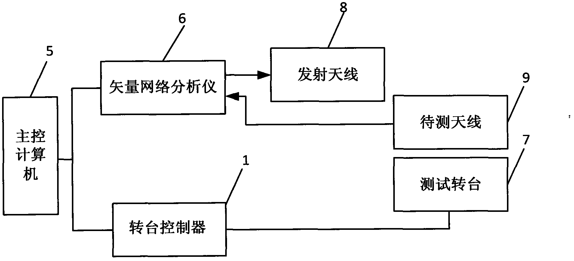
technical field [0001] The invention relates to the technical field of testing, in particular to a fast antenna testing device based on hardware triggering, and also to a fast antenna testing method based on hardware triggering. Background technique [0002] For the antenna test, from the perspective of the hardware system, its functional block diagram is as follows figure 1 As shown, it includes a main control computer 5, a vector network analyzer 6, a test turntable 7, a turntable controller 1, a transmitting antenna 8 and an antenna to be tested 9, and each part completes the test work through coordination and cooperation. Taking the far-field test as an example to introduce the specific test process of the system: firstly, the antenna 9 to be tested is set up on the test turntable 7, and the transmitting antenna 8 and the antenna 9 to be tested are placed relative to each other at a certain distance; The signal that the vector network analyzer 6 produces is radiated out...

Claims


Application Information

Patent Timeline
IPC IPC(8): G01R29/10
Inventor 王亚海常庆功唐敬双赵锐张文涛刘伟杜刘革殷志军
Owner CHINA ELECTRONIS TECH INSTR CO LTD
Learn More