

Method for rectifying mine transient electromagnetic inductive effect by utilizing emission current
A transient electromagnetic and inductive effect technology, applied in the field of geophysical exploration, can solve problems such as not participating in data processing, difficult to meet actual engineering, and affecting the accuracy of data mathematical interpretation, so as to remove inductive effect, increase the usable range, and ensure safe production Effect
Inactive Publication Date: 2013-08-28
XIAN RES INST OF CHINA COAL TECH& ENG GROUP CORP
View PDF2 Cites 5 Cited by
- Summary
- Abstract
- Description
- Claims
- Application Information
AI Technical Summary
Problems solved by technology
Due to the limitation of underground construction space, this method cannot use the large emission wire frame (generally with a side length greater than 100m) that is routinely used on the ground, and often uses a multi-turn small wire frame with a side length less than 2m, which will cause bands in the original sampling data. The influence of wireframe self-inductance and mutual inductance that cannot be ignored makes the measured mine transient electromagnetic secondary field attenuation curve quite different from the ground large wireframe transient electromagnetic secondary field attenuation curve, which makes many more mature processing and inversion The method cannot be applied, which affects the accuracy of data mathematical interpretation, and is difficult to meet the needs of actual engineering
[0003] At present, there is no technology to remove the influence of the inductance effect from the data. The general method is to directly delete the early affected data without participating in the data processing, so that there will be shallow blind spots in the interpretation results.
Method used
View moreImage
Smart ImageViewing Examples

Examples
Embodiment
[0054] b a n I
[0055]
Login to View More PUM
 Abstract
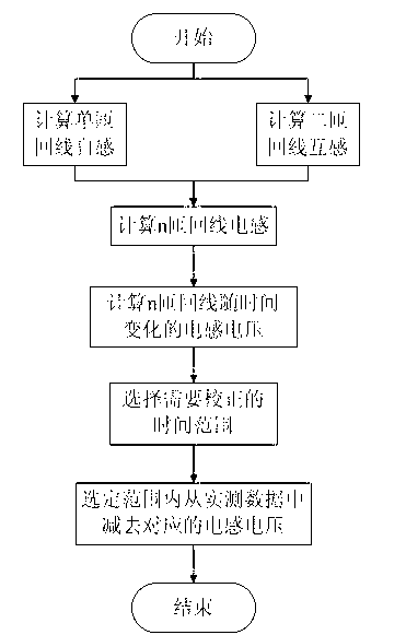
The invention relates to the technical field of geophysical exploration, in particular to a method for rectifying a mine transient electromagnetic inductive effect by utilizing an emission current. The method is used for rectifying the inductive effect which is brought by a plurality of turns of small wire frames to data collection, wherein the small wire frames are used by mine transient electromagnetism, and the effect brought by the inductive effect in the process of processing the transient electromagnetism of an existing mine is eliminated. The method comprises a first step of starting, a second step of calculating single-turn return wire self-inductance and double-turn return wire mutual inductance, a third step of calculating inductance of n turns of return wires, a fourth step of calculating inductance voltage, changed as time goes, of the n turns of the return wires, a fifth step of selecting a time range needing to be rectified, a sixth step of subtracting corresponding inductance voltage in measured data within the selected range to obtain induced electromotive force of the rectified mine transient electromagnetism, and a seventh step of finishing.
Description
1. Technical field: [0001] The invention relates to the technical field of geophysical exploration, in particular to a method for correcting the transient electromagnetic inductance effect of a mine by using emission current. 2. Background technology: [0002] Mine transient electromagnetic method, referred to as mine TEM, is an electromagnetic exploration method that has been widely used in the fields of coal mine advanced exploration, roof and floor water damage detection, side walls and internal water damage detection of working faces in recent years. Due to the limitation of underground construction space, this method cannot use the large emission wire frame (generally with a side length greater than 100m) that is routinely used on the ground, and often uses a multi-turn small wire frame with a side length less than 2m, which will cause bands in the original sampling data. The influence of wireframe self-inductance and mutual inductance that cannot be ignored makes the m...
Claims
Login to View More Application Information
Patent Timeline
 IPC IPC(8): G01V13/00G01V3/28
Inventor范涛赵兆王继矿吴迪宁殿艳鲁晶津
OwnerXIAN RES INST OF CHINA COAL TECH& ENG GROUP CORP