
On-orbit maintenance method for star sensor

A technology of star sensor and maintenance module, applied in instruments, static memory, read-only memory, etc., can solve problems such as unfavorable software design improvement, comparison and verification, data channel injection program implementation error, and inability to restore to the original state, etc. The whole process is autonomously controlled, the design is fast and simple, and the effect of reducing process risks

Active Publication Date: 2013-08-28
BEIJING INST OF CONTROL ENG
View PDF3 Cites 10 Cited by
  • Summary
  • Abstract
  • Description
  • Claims
  • Application Information

AI Technical Summary

Problems solved by technology

[0007] The implementation of the above two on-orbit maintenance methods requires modification of the original program code, and the risk is relatively high. If an error occurs in the data channel during the injection process or the injection program itself is implemented incorrectly, it will have a great impact on the original program or even fail. normal work
The algorithm design of the star sensor will also be improved based on the analysis of on-orbit data. There are many on-orbit test items. Since each program injection process is a new operation, it cannot be restored to the original state once it starts, which is not conducive to the improvement of software design. Compare and verify
At the same time, since the modification of the program memory is involved, the above method is only applicable to E 2 For the star sensor with PROM type program memory, if all the software is solidified in the PROM for high hardware reliability during the design of the star sensor product, you cannot directly modify the E 2 PROM or SRAM achieves the purpose of on-orbit maintenance, which greatly limits its use conditions

Method used


Image

  • On-orbit maintenance method for star sensor
  • On-orbit maintenance method for star sensor
  • On-orbit maintenance method for star sensor

Examples


Embodiment Construction

[0037] The specific design method and implementation of the invention will be further described in detail below in conjunction with the accompanying drawings.

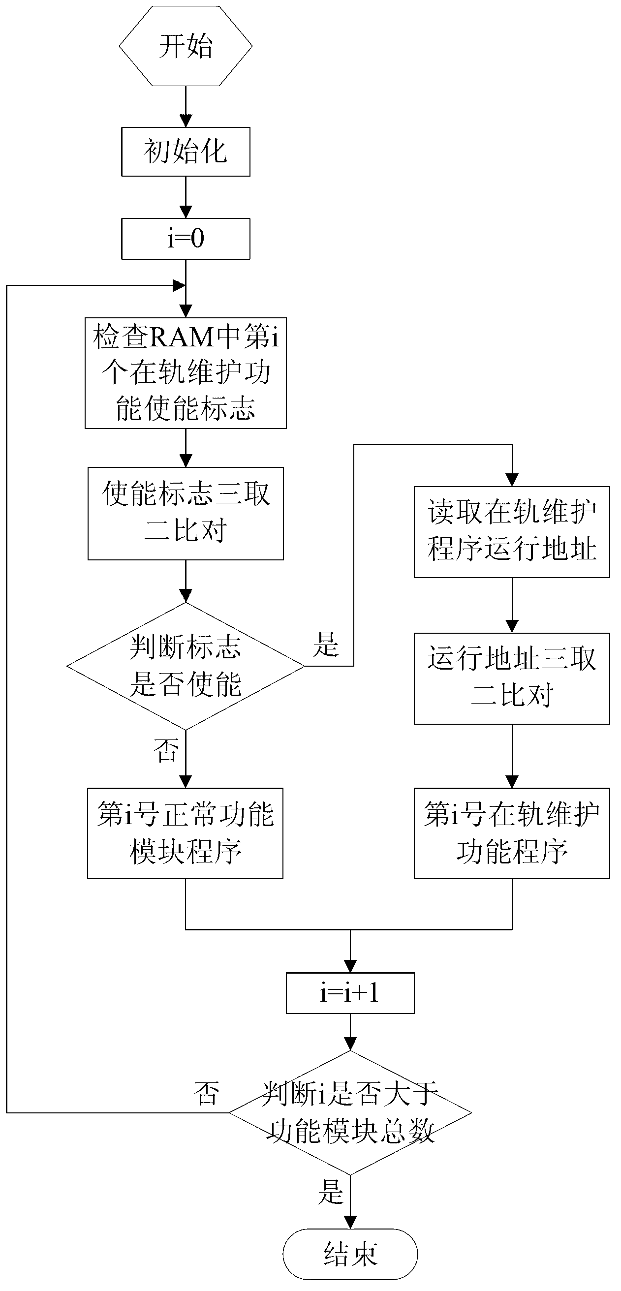
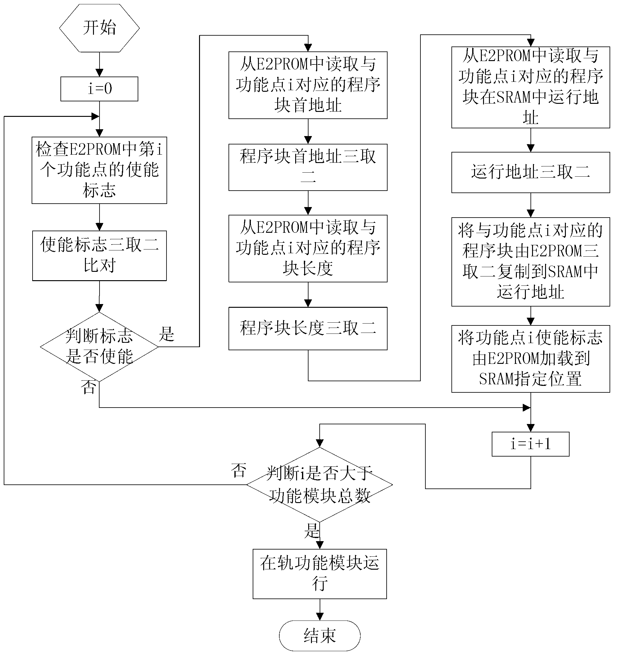
[0038]The software reliability of the star sensor is continuously improved through ground verification and on-orbit tests. In order to ensure that when problems occur in the star sensor, risk control and problem solving can be carried out through software means. The software on-orbit maintenance method must be designed. Through The on-orbit modification of the software is completed by ground remote command injection. Due to the slow injection speed of ground remote control commands and the relatively large amount of injected data, as well as the constraints of satellite orbits and station distribution, a complete on-orbit maintenance process usually requires the maintenance program to be injected in multiple orbital circles , Occupying relatively large satellite management resources. The design of the software on-orbi...


PUM


Abstract

An on-orbit maintenance method for a star sensor comprises E<2>PROM (electrically erasable programmable read-only memory) based maintenance of application programs in a program storage on the star sensor and SRAM (static random access memory) based maintenance of the application programs in the program storage on the star sensor, the application programs are decomposed according to functions and divided into a plurality of functional modules, all the functional modules are numbered, each functional module corresponds to an independent on-orbit maintenance module in an idle E<2>PROM or SRAM space, and enabling and operation of maintenance functions are completed according to states of the on-orbit maintenance modules when the functional modules of the application programs operate. According to the on-orbit maintenance method, the universal on-orbit maintenance method is designed for different hardware program storages, corresponding on-orbit maintenance areas are configured for all functional areas, maintenance programs are directly injected into the maintenance areas in an on-orbit mode, the original programs are not required to be modified, the on-orbit injection programs are quick and simple to design, and the reliability is high.

Description

technical field [0001] The invention relates to an on-orbit maintenance method for a star sensor, which can realize the modification of the star sensor software on the star to improve the reliability of the software, solve the on-orbit fault of the star sensor, and perfect and improve the design of the whole machine. Background technique [0002] The star sensor takes the star as the measurement target and provides high-precision attitude measurement data for the satellite. It is one of the most important and basic stand-alone products in satellite control. In recent years, during the development process of star sensor products and on-orbit flight tests, some software-related problems have occurred and been discovered, some of which are caused by certain deficiencies in the software itself, which sometimes cause the functions and performance of star sensors to fail to meet mission requirements. , part of the problems that belong to the hardware need to be made up by the soft...

Claims


Application Information

Patent Timeline
IPC IPC(8): G06F11/36
CPCG06F9/445G06F11/00G06F11/1433G11C7/20G11C16/20
Inventor 郑然武延鹏张巍李昊然严微王晓燕高文文
Owner BEIJING INST OF CONTROL ENG
Learn More