Retaining device for substrates and method for coating a substrate

A retainer and coating technology, which is used in semiconductor/solid-state device manufacturing, coating, sputtering, etc., and can solve the problems of insufficient grade purity and inability to exclude particles from falling on the surface of the substrate to be coated.

Inactive Publication Date: 2013-08-28
FRAUNHOFER GESELLSCHAFT ZUR FOERDERUNG DER ANGEWANDTEN FORSCHUNG EV
View PDF6 Cites 5 Cited by
  • Summary
  • Abstract
  • Description
  • Claims
  • Application Information

AI Technical Summary

Problems solved by technology

However, a disadvantage in this way is that the possibility of particles falling onto the surface of the substrate to be coated cannot be ruled out due to gravity, so that an insufficient level of purity may be obtained during the coating process

Method used


Image

  • Retaining device for substrates and method for coating a substrate
  • Retaining device for substrates and method for coating a substrate
  • Retaining device for substrates and method for coating a substrate

Examples


Embodiment Construction

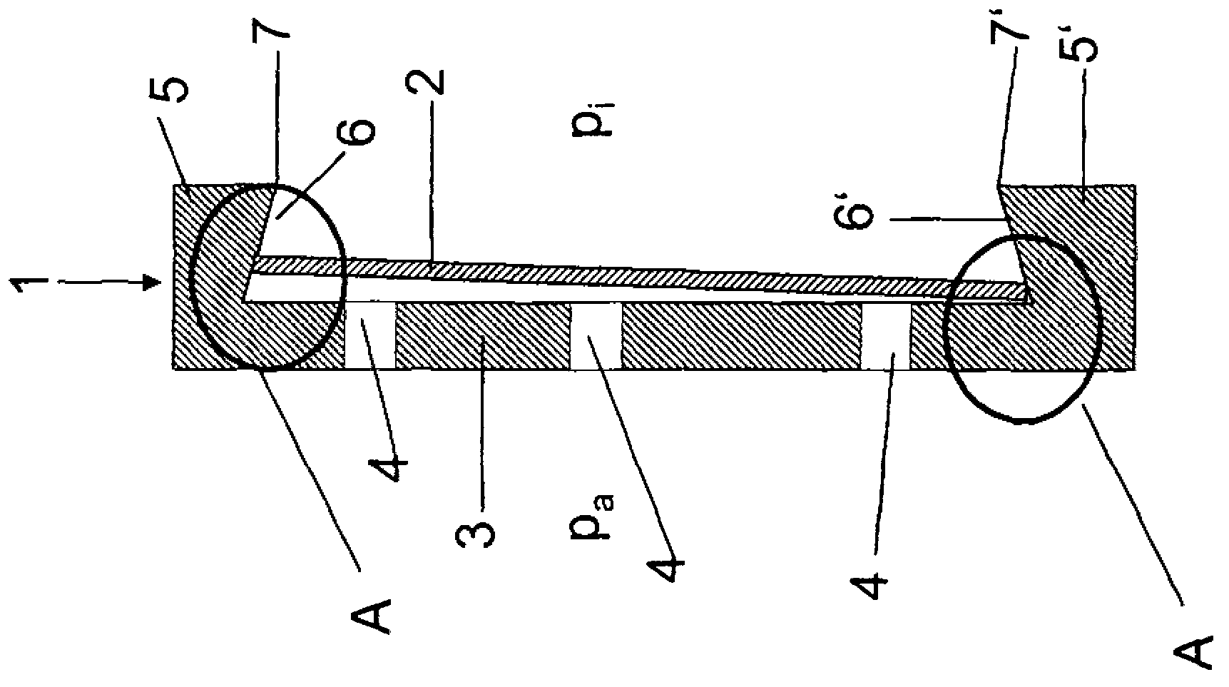
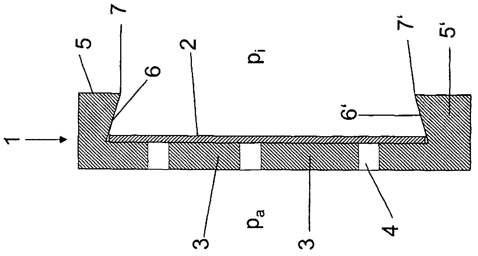
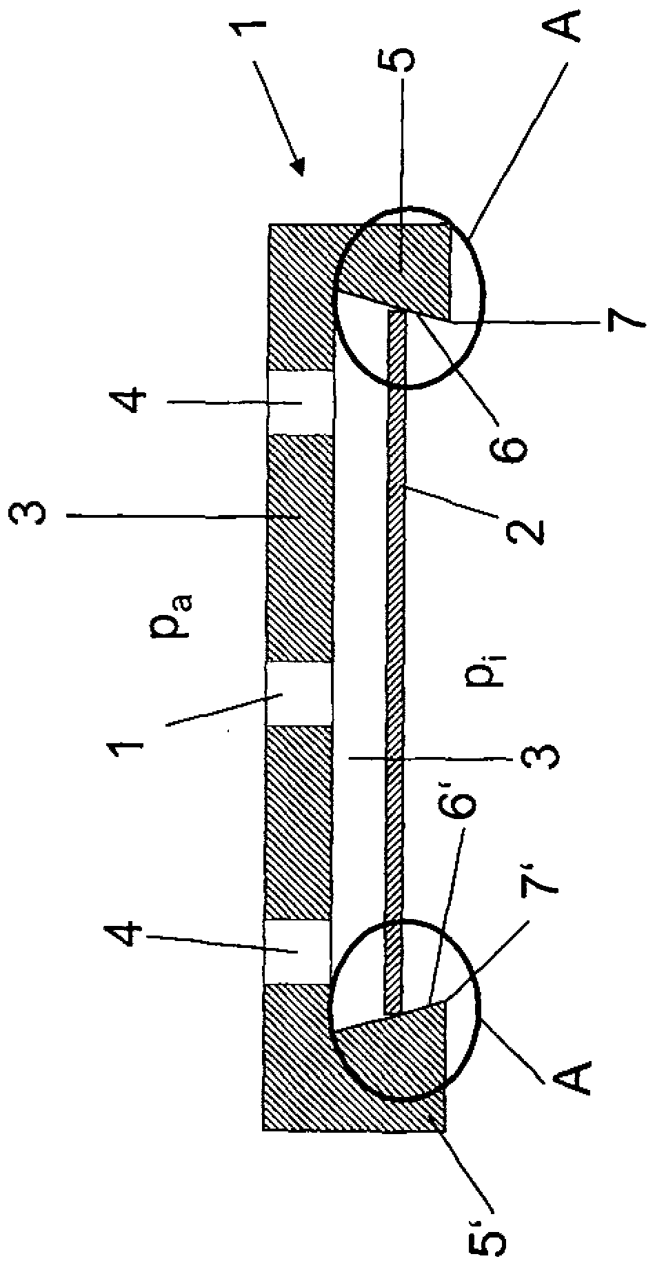
[0046] Figure 1 shows a retainer 1 according to the invention placed vertically, first before substrate suction ( Figure 1a ), followed by basal inhalation ( Figure 1b ). Thus, the retainer 1 comprises a support device 3 , which may also be referred to as a base bracket, and three apertures 4 positioned continuously through the support device 3 in the form of through holes in the section shown. Two arms (arm 5 and arm 5 ′) integrally formed with the support device 3 are flanked on both sides of the support device 3 . Therefore, the arm 5 and the arm 5' respectively have an inner wall 6 and an inner wall 6', and the inner wall 6 and the inner wall 6' have chamfered structures. In the case of the device 1 shown here, the angle at which the walls 6 , 6 ′ each surround the support surface of the substrate carrier 3 for the substrate 2 is, for example, approximately 75°. However, larger or smaller angles are also possible. Likewise, the angles of the arms 5 and 5' can also be ...


PUM


Abstract

The invention relates to a retaining device for substrates to be coated, which device comprises a contact surface for the substrate to be coated. The retaining device is for example configured as a plate on which the substrate rests and which has one or more apertures, e.g. drilled holes, grooves etc. has, through which a pressure gradient can be set between the face of the substrate and the opposite face of the retaining device. In this way a temporary fixing of the substrate by suction onto the retaining device is possible. The invention also relates to a method for coating a substrate which uses the retaining device according to the invention.

Description

technical field [0001] The invention relates to a retainer for a substrate to be coated, the retainer comprising a support surface for the substrate to be coated. For example, the retainer is configured as a flat plate on which the substrate is supported, whereby the flat plate has one or more openings (such as through holes, grooves, etc.) A pressure gradient is provided between the oppositely positioned retainer sides. As a result, it is possible to temporarily fix the substrate on the retainer by suction. Furthermore, the invention relates to a method for coating a substrate using a retainer according to the invention. Background technique [0002] In order to reduce the costs of coating, it must be possible to adjust the dimensions of the coating equipment as best as possible. Therefore, the following requirements are revealed: [0003] a) Particles from the coating process or possible transport processes must not fall onto the surface of the area to be coated. This...

Claims


Application Information

Patent Timeline
Patent Type & Authority Applications(China)
IPC IPC(8): C23C14/50C23C16/458H01L21/683B25J15/06
CPCC23C14/50C23C16/4585C23C16/4586C23C16/4587H01L21/67346H01L21/6838C23C16/458
Inventor 斯蒂芬·雷伯诺伯特·希林格马丁·阿诺德戴维·波卡扎
Owner FRAUNHOFER GESELLSCHAFT ZUR FOERDERUNG DER ANGEWANDTEN FORSCHUNG EV
Why Eureka
Try Eureka