Gas-turbine combustion chamber with fuel nozzle, burner with such a fuel nozzle and fuel nozzle

A gas turbine and fuel nozzle technology, applied in gas fuel burners, burners, combustion chambers, etc., can solve problems such as shortening the service life of fuel nozzles, and achieve good cooling effects

Inactive Publication Date: 2013-08-28
SIEMENS AG
View PDF7 Cites 3 Cited by
  • Summary
  • Abstract
  • Description
  • Claims
  • Application Information

AI Technical Summary

Problems solved by technology

This shortens the service life of the entire fuel nozzle

Method used


Image

  • Gas-turbine combustion chamber with fuel nozzle, burner with such a fuel nozzle and fuel nozzle
  • Gas-turbine combustion chamber with fuel nozzle, burner with such a fuel nozzle and fuel nozzle
  • Gas-turbine combustion chamber with fuel nozzle, burner with such a fuel nozzle and fuel nozzle

Examples


Embodiment Construction

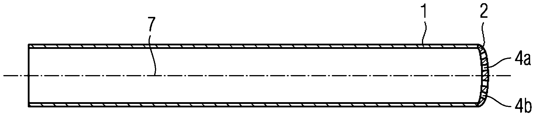
[0019] figure 1 A fuel nozzle with a cylindrical nozzle tube 1 and a convex nozzle cover 2 is shown. The fuel nozzle 1 has a cylinder axis 7 . A fluid, in particular fuel, is introduced into the fuel nozzle 1 and then exits through the through-openings 4a, 4b to a downstream, not shown combustion chamber.

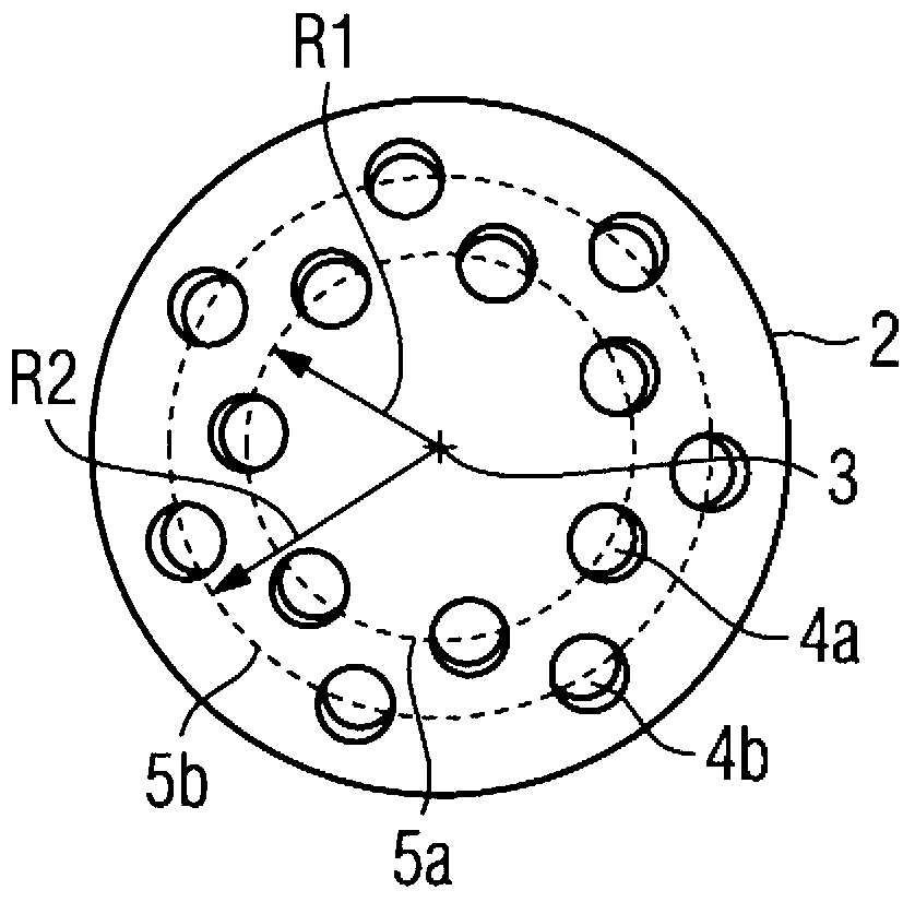
[0020] figure 2 The nozzle cover 2 is shown viewed from the front. The nozzle cover 2 has a center point 3 . Furthermore, the nozzle cover 2 has a plurality of throughflow openings 4a, 4b. The through-openings 4 a , 4 b are arranged on at least two annular lines 5 a , 5 b at different radial distances R1 , R2 from the center point 3 . Wherein, the through hole 4a is arranged on a circular line 5a whose distance from the center point 3 is a radius R1. At this time, the ring line 5a having the smaller radius R1 is referred to as the radially inner ring line 5a. In contrast to the nozzles of the prior art, multiple fuels or (if the fuels are premixed) multiple fuel-ai...


PUM


Abstract

The invention relates to a gas-turbine combustion chamber with a fuel nozzle comprising a cylindrical nozzle tube (1), into which a fluid is made to flow, and a convexly formed nozzle cover (2), which is arranged downstream of the nozzle tube (1) and has a central point (3), wherein the nozzle cover (2) has a number of through-openings (4a, 4b), through which the fluid that is made to flow into the nozzle tube (1) leaves, wherein the through-openings (4a, 4b) are arranged at different radial distances (R1, R2) from the central point (3) on at least two circular lines (5a, 5b).

Description

technical field [0001] The invention relates to a gas turbine combustor with at least one fuel nozzle according to the preamble of claim 1 . Furthermore, the invention relates to a burner with a fuel nozzle of the type described in claim 10 . Furthermore, the invention relates to a fuel nozzle according to claim 11 . Background technique [0002] In view of the global effort to reduce pollutant emissions from combustion equipment especially on gas turbines, burners and operating methods for burners have been improved in recent years so that these burners have particularly low nitrogen oxides (NOx) emissions. In addition, it is often emphasized that such burners can use not only one fuel, but also a wide variety of fuels, such as oil, natural gas and / or low-calorie fuels (hereinafter also referred to as synthesis gas), which can be used. Selectively work individually or in combination, thereby increasing the safety of fuel supply and the flexibility of operation. [0003]...

Claims


Application Information

Patent Timeline
Patent Type & Authority Applications(China)
IPC IPC(8): F23D11/12F23D14/08F23D14/58F23R3/34F23R3/36F02M61/18
CPCF23C2900/07021F23D11/12F23D14/58F23D2900/14003F23D2900/14642F23R3/346F23R3/36F23R2900/00002F02C7/22
Inventor J.范卡姆彭T.A.福克斯S.威廉斯U.沃尔兹U.格鲁施卡
Owner SIEMENS AG
Why Eureka
Try Eureka