Man-machine interactive manipulator control system and method based on binocular vision

A binocular vision and control system technology, applied in manipulators, program-controlled manipulators, manufacturing tools, etc., can solve the problems of inability to accurately detect the position and attitude of working objects, not in place, inconvenient, etc.

Inactive Publication Date: 2013-09-04
SHANDONG UNIV OF SCI & TECH
View PDF8 Cites 71 Cited by
  • Summary
  • Abstract
  • Description
  • Claims
  • Application Information

AI Technical Summary

Problems solved by technology

[0008] 3. The working position of the robot is changing, and it is impossible to accurately detect the position and attitude of the working object. At present, the robot is controlled by the master-slave operation mode, that is, through the operation of the "master hand" handle or button, to control the robot. Adjust the movement position of the "slave hand" (that is, the manipulator that actually operates the work) at any time to make the robot operate on the target, and personnel are closely involved in its operation process, such as a master-slave operation riot robot, etc.
[0010] (1). The operator must manipulate all the joints of the "master hand" to make the "slave hand" make corresponding movements. The whole control process is complicated and lengthy
[0011] (2). Due to the error of the operator's visual inspection and the difficulty of accurately controlling the operating range of the "main hand", in the process of adjusting the "main hand", the "slave hand" often moves "not in place" or "moves out of place". , it needs multiple adjustments to make the "slave hand" reach the required position, which is very inconvenient

Method used


Image

  • Man-machine interactive manipulator control system and method based on binocular vision
  • Man-machine interactive manipulator control system and method based on binocular vision
  • Man-machine interactive manipulator control system and method based on binocular vision

Examples


Embodiment Construction

[0040] The implementation of the present invention will be further described below according to the accompanying drawings.

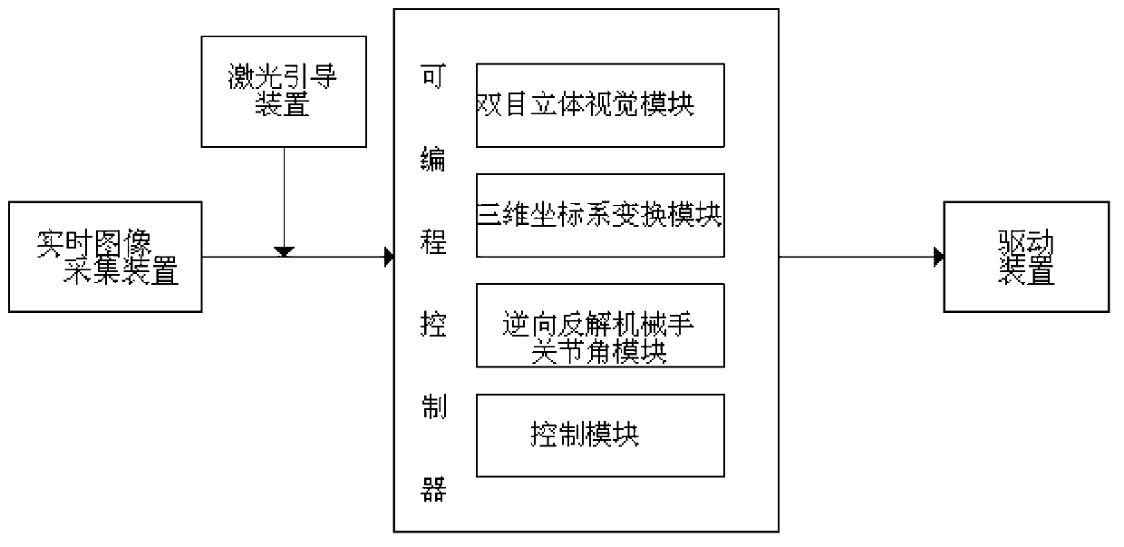
[0041] figure 1 It is a schematic block diagram of the system of the present invention. It can be seen from the figure that it includes four major parts, namely: a real-time image acquisition device, a laser guidance device, a binocular stereo vision module, a three-dimensional coordinate system transformation module, and a reverse anti-analysis manipulator joint angle module. A programmable controller composed of a control module and a drive module. in:

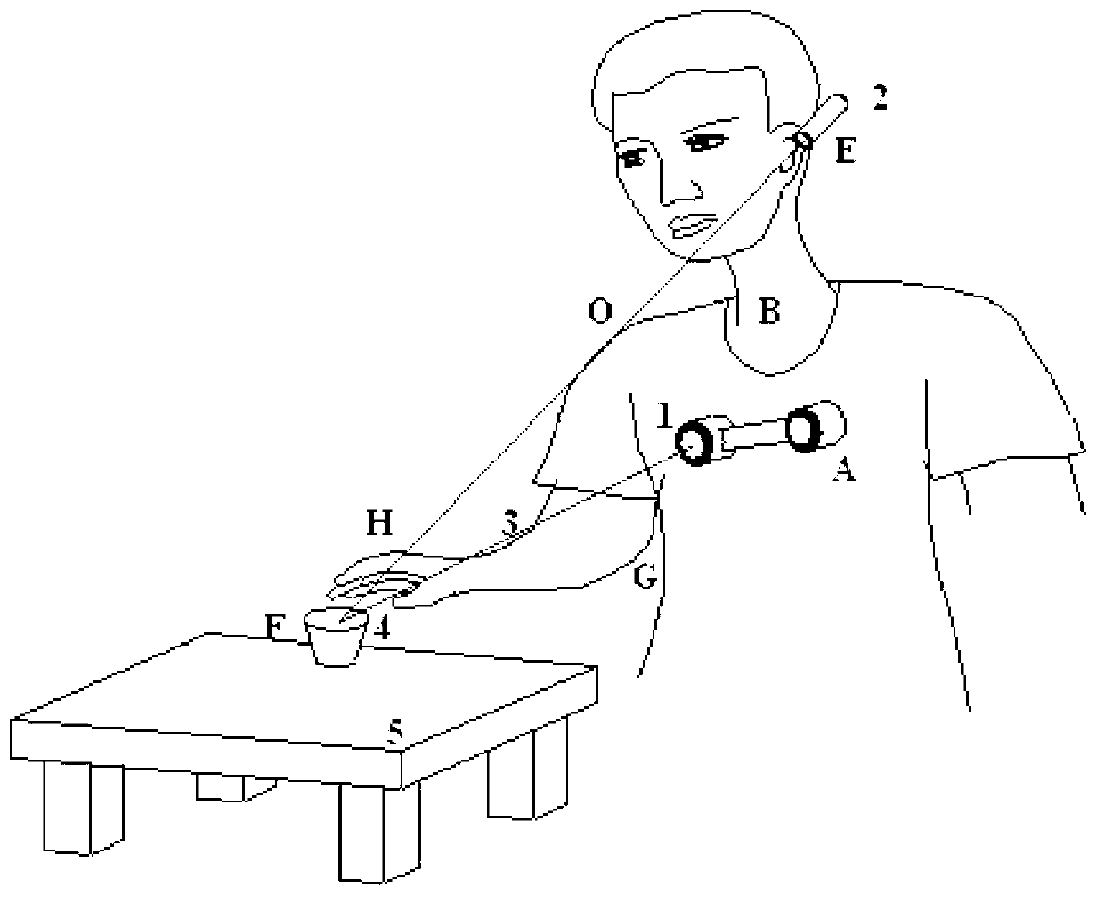
[0042] The embodiment of the real-time image acquisition module is for example figure 2 As shown, it is a binocular camera 1 placed at point A on the chest of a patient with a disabled limb. The first function is to provide real-time video streams for man-machine interactive control of the manipulator operation, so that the manipulator controller can obtain the visual field information in front of h...


PUM


Abstract

The invention discloses a man-machine interactive manipulator control system and method based on binocular vision. The man-machine interactive manipulator control system is composed of a real-time image collecting device, a laser guiding device, a programmable controller and a driving device. The programmable controller is composed of a binocular three-dimensional vision module, a three-dimensional coordinate system transformation module, an inverse manipulator joint angle module and a control module. Color characteristics in a binocular image are extracted through the real-time image collecting device to be used as a signal source for controlling a manipulator, and three-dimensional information of red characteristic laser points in a view real-time image is obtained through transformation and calculation of the binocular three-dimensional vision system and a three-dimensional coordinate system and used for controlling the manipulator to conduct man-machine interactive object tracking operation. The control system and method can effectively conduct real-time tracking and extracting of a moving target object and is wide in application fields such as intelligent artificial limb installing, explosive-handling robots, manipulators helping the old and the disabled and the like.

Description

technical field [0001] The invention relates to manipulator control technology in the fields of rehabilitation aids, robotics, etc., and in particular to manipulator control technology using human-computer interaction, which is an intelligent control and efficient method based on machine vision recognition and positioning. Background technique [0002] With the development and progress of science and technology, the application field of manipulator is gradually extended. Manipulators are not only widely used in traditional industries, such as construction, mining, metallurgy, petroleum, chemical industry, shipbuilding and other fields, but also have been expanded to high-tech fields such as nuclear energy, aerospace, biochemistry, etc. At the same time, they have also begun to be used in home health care, medical care and other services Industrial fields, such as intelligent artificial limbs, robotic hands for the elderly and the disabled, etc. At present, how to convenient...

Claims


Application Information

Patent Timeline
Patent Type & Authority Applications(China)
IPC IPC(8): A61F2/70B25J3/00B25J9/18
Inventor 樊炳辉张发王传江张坤陈毕胜
Owner SHANDONG UNIV OF SCI & TECH
Why Eureka
Try Eureka