Plane milling and boring machine tool rest

A boring and milling machine and tool holder technology, which is applied in the field of gantry boring and milling machine tool holders, can solve the problems of low positioning accuracy and troublesome clamping, achieve high positioning accuracy, increase processing efficiency and precision, and reduce labor intensity of workers

Inactive Publication Date: 2013-09-04
JIANGSU UNIV OF SCI & TECH
View PDF4 Cites 1 Cited by
  • Summary
  • Abstract
  • Description
  • Claims
  • Application Information

AI Technical Summary

Problems solved by technology

However, the taper of the inner hole of most large propellers is usually between 1° and 20°. Traditional machining needs to complete the boring of the hole and the milling of the blade surface on a boring machine and a milling machine respectively. The clamping is more troublesome and the positioning accuracy is low.

Method used


Image

  • Plane milling and boring machine tool rest
  • Plane milling and boring machine tool rest
  • Plane milling and boring machine tool rest

Examples


Embodiment Construction

[0012] Below in conjunction with accompanying drawing and specific embodiment, further illustrate the present invention, should be understood that these embodiments are only for illustrating the present invention and are not intended to limit the scope of the present invention, after having read the present invention, those skilled in the art will understand various aspects of the present invention Modifications in equivalent forms all fall within the scope defined by the appended claims of this application.

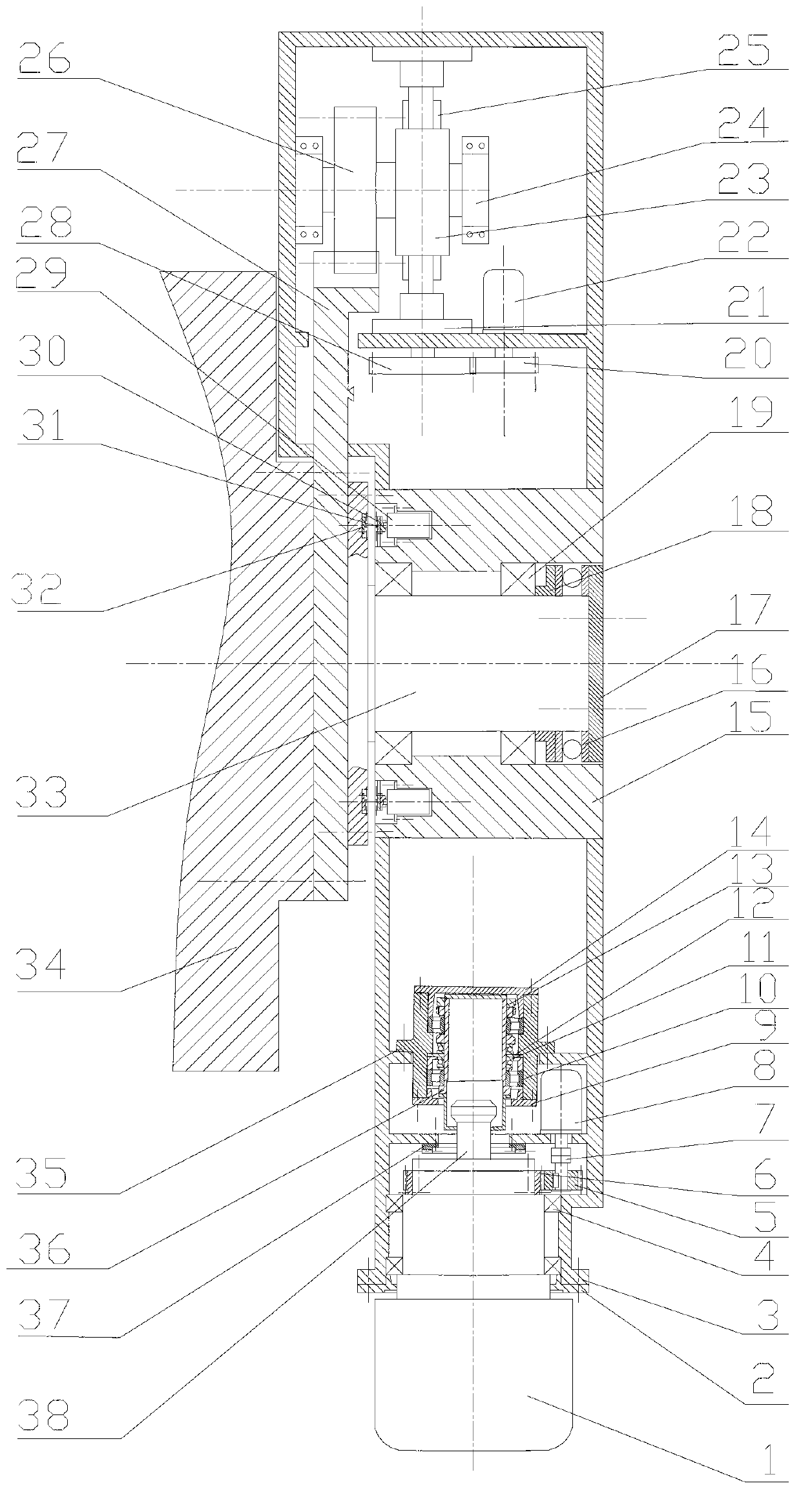
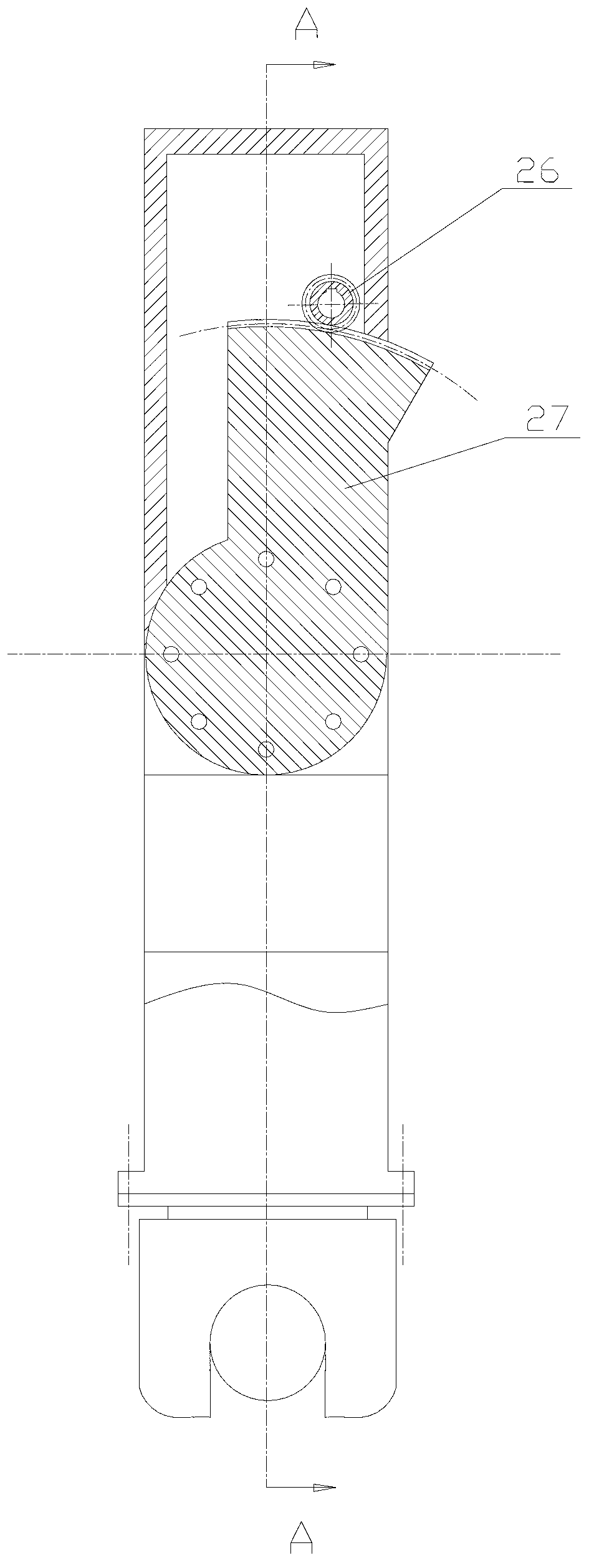
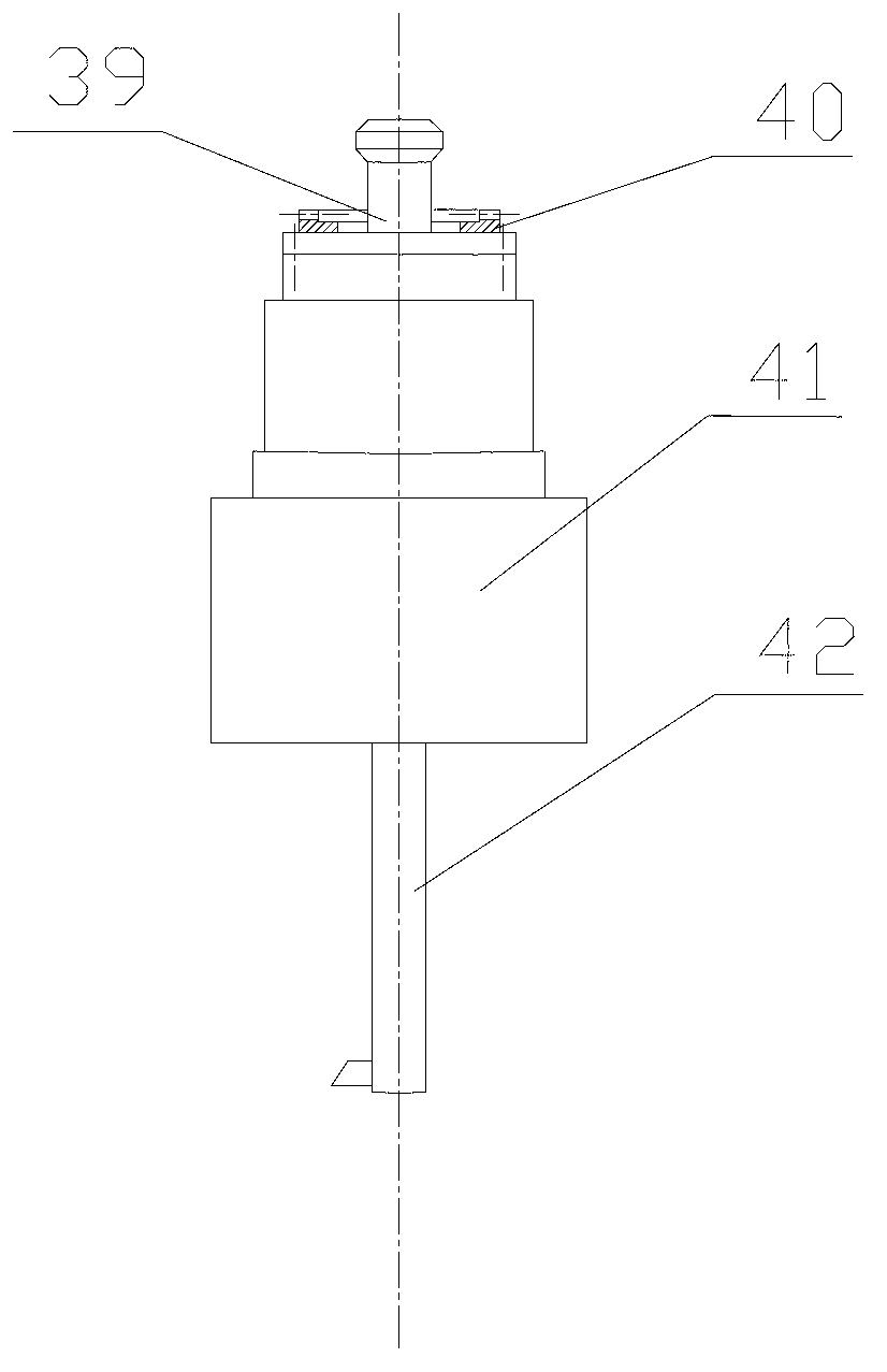
[0013] see Figure 1 to Figure 3 As shown, among them, figure 1 yes figure 2 A-A sectional view in . The invention discloses a tool holder for a gantry boring and milling machine, which includes a milling cutter head, a boring cutter head, a ram 34, a central shaft 33, an indexing mechanism and a tool holder; The cutter head or boring cutter head is installed at one end of the tool holder; the indexing mechanism is fixedly connected with the cutter holder; the millin...


PUM


Abstract

The invention discloses a plane milling and boring machine tool rest comprises a milling tool bit, a boring tool bit, a ram, a central shaft, an indexing mechanism and a tool rest body. The tool rest body is rotationally connected with the central shaft. The milling tool bit or the boring tool bit is mounted at one end of the tool rest body. The indexing mechanism is fixedly connected with the tool rest body. The milling tool bit comprises a five-axis milling head and a milling head pull rod which are fixedly connected. The boring tool bit comprises a boring tool rest pull rod, a lower-end fluted disc, a boring tool rest and a boring tool bar, wherein the boring tool rest pull rod and the lower-end fluted disc are fixedly connected at the upper end of the boring tool rest, and the boring tool bar is fixedly connected at the lower end of the boring tool rest. By the boring tool rest pull rod, indexing adjustment of the ram in a range of 1-20 degrees can be achieved, simple switch of the milling tool bit and the boring tool bit can be achieved, especially in machining of large workpieces, complex curve face milling, taper hole boring and excircle surface cutting can be completed after one-step mounting, machining efficiency and precision of the large workpieces are increased greatly, repeated positioning errors caused by secondary clamping are avoided.

Description

technical field [0001] The invention relates to a tool holder for a gantry boring and milling machine, in particular to a tool holder for a gantry boring and milling machine capable of milling curved surfaces with five degrees of freedom and boring taper holes. Background technique [0002] With the development of manufacturing technology, the five-axis linkage CNC machine tool system has become the guarantee for solving complex curved surface milling and improving processing efficiency and precision. The five-axis linkage CNC boring and milling machine is widely used in the processing of many large workpieces, such as the processing of large propeller blades. The taper of the inner hole of most large propellers is usually between 1° and 20°. Traditional machining requires the boring of the hole and the milling of the blade surface on a boring machine and a milling machine. The clamping is cumbersome and the positioning accuracy is low. Contents of the invention [0003] ...

Claims


Application Information

Patent Timeline
Patent Type & Authority Applications(China)
IPC IPC(8): B23B21/00
Inventor 任家隆吴宏伟赵礼刚吴爱胜夏添尹宛馨陈丹丹连立麟于风侠
Owner JIANGSU UNIV OF SCI & TECH
Why Eureka
Try Eureka