Bar conveyer

A feeder and bar technology, applied in the field of mechanical processing, can solve the problems that cannot be solved comprehensively and effectively, failure of conveying, insufficient clamping force, etc., and achieve simple and compact machine structure, saving space and cost, and high tensile strength Effect

Active Publication Date: 2013-09-04
台州市良曜成套设备有限公司
View PDF6 Cites 18 Cited by
  • Summary
  • Abstract
  • Description
  • Claims
  • Application Information

AI Technical Summary

Problems solved by technology

Although this utility model partially solves the shortcomings of the roller group structure listed above, it cannot fully and effectively solve it, and also produces some new shortcomings, which are not conducive to actual production and application.
For example: 1. Although the track made of rubber can protect materials with low surface hardness; but because of its soft material, it will produce clamping creep, resulting in insufficient actual clamping force; when transporting hard bars or conveying When the resistance is high, the rubber track will be easily worn or broken
2. Since the structure is fixed with a set of pulleys on the upper and lower mounting plates, the clamping method is to promote the movement and clamping of the upper and lower mounting plates as a whole; instead of active clamping of the pulleys, it cannot be effectively clamped. Clamp feeding of bent bars
3. In the clamping and feeding area of ​​this structure, there are only up and down but no left and right limit guide functions, and the continuous feeding function of the front and rear bars closely connected to each other cannot be reliably realized.
4. According to the content of the patent specification, the clamping method of the structure to the bar is to use the connecting bolt to pass through the upper and lower mounting plates, and the bolts are sleeved with compression springs to act on the upper and lower mounting plates to achieve clamping; this The clamping force of this clamping method is not enough and unstable, and the operation is extremely inconvenient
5. The track made of rubber described in this structure is socketed on two rollers. When the track encounters conveying resistance, it will slip with the socketed rollers, resulting in conveying failure

Method used


Image

  • Bar conveyer
  • Bar conveyer
  • Bar conveyer

Examples


Embodiment 1

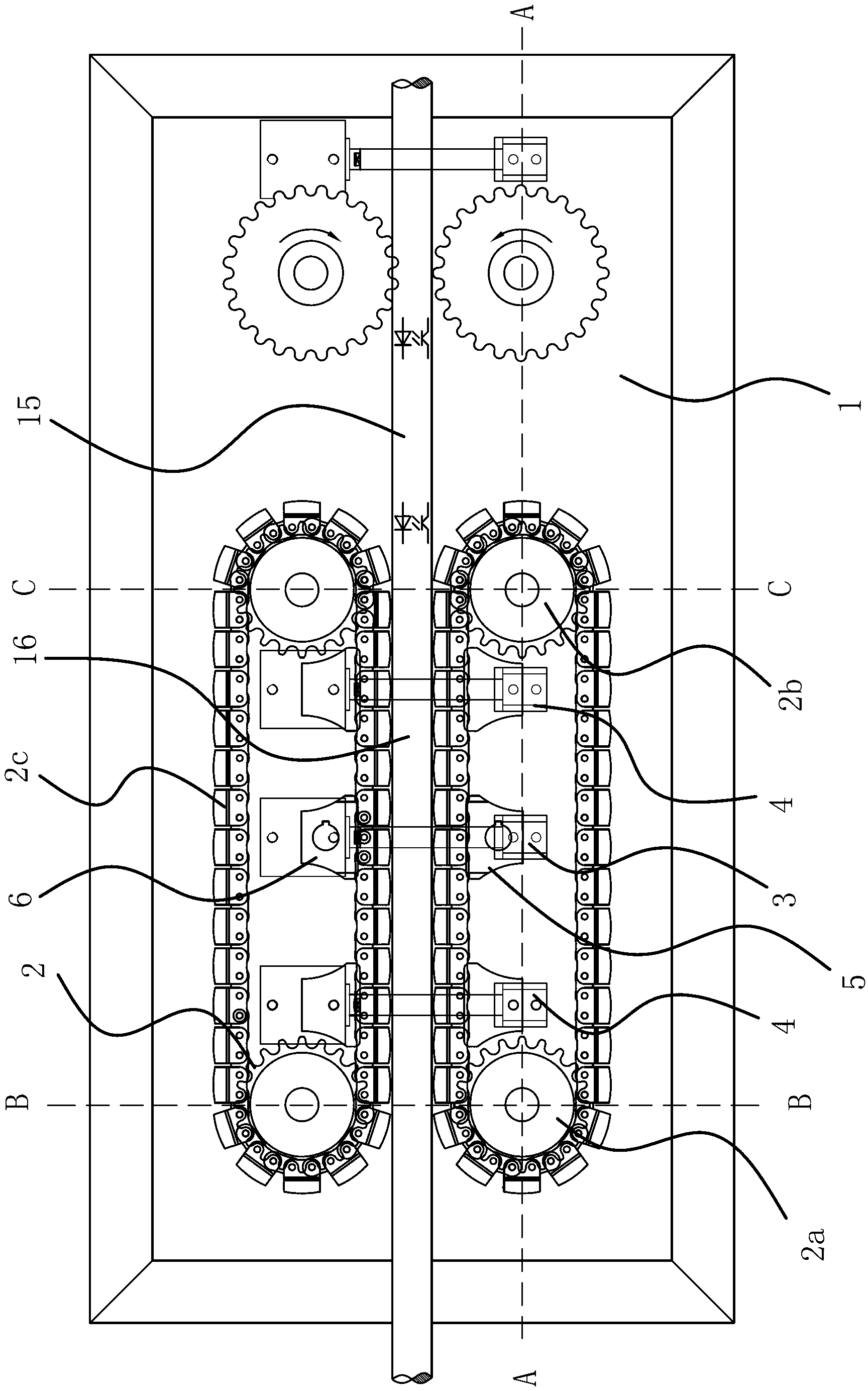
[0038] The present invention is suitable for automatic feeding of straight metal bars 15 and can be used in conjunction with punches, sawing machines, hydraulic shears, etc. to complete the automatic feeding and cutting work of straight bars 15. Such as figure 1 , figure 2 , Figure 4 As shown, the present bar feeder includes a frame 1 and two groups of horizontally opposed conveying crawler pairs 2, and a bar clamping area 16 is formed between the two groups of conveying crawler pairs 2. The conveyor pair 2 includes a driving wheel 2a, a driven wheel 2b, and a crawler 2c. The frame 1 is provided with a driving member that can drive at least one set of the driving wheel 2a of the conveyor pair 2 to rotate. Between the conveyor pair 2 and the frame 1 An adjustment mechanism that can increase or decrease the width of the bar clamping area 16 is provided.

[0039] Specifically, the adjustment mechanism includes a first clamping cylinder 3 and two sets of second clamping cylinders 4...

Embodiment 2

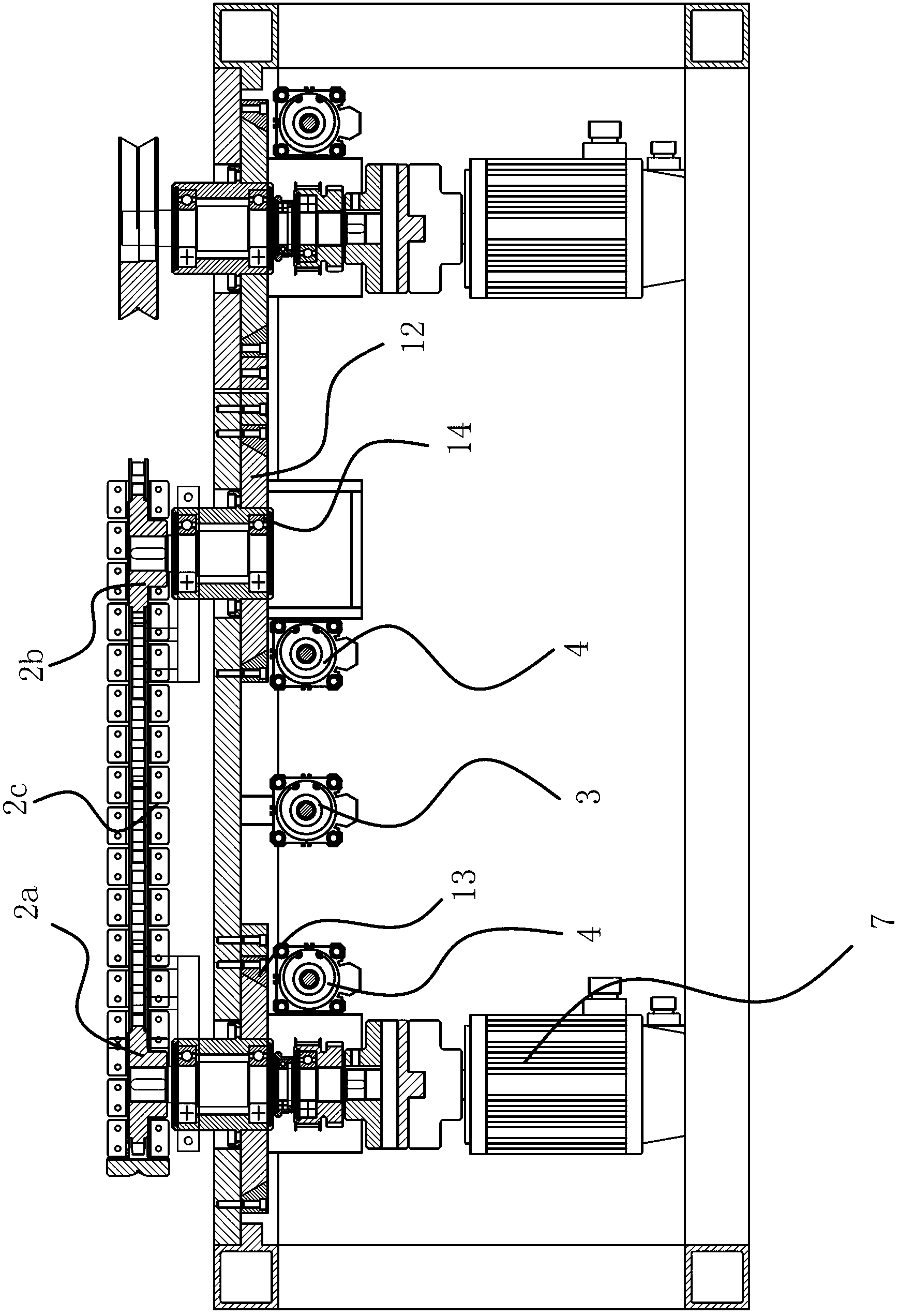
[0045] The structure of this embodiment is basically similar to that of the first embodiment. The difference is that the driving member includes two motors 7, and the two motors 7 and the two driving wheels 2a are connected in a one-to-one correspondence through universal joints. The two driving wheels 2a have their own driving parts, so there is no need for a synchronous transmission structure.

[0046] In addition, the adjustment mechanism of this embodiment includes a first abutment member 5, the first abutment member 5 is located inside a set of conveyor belt pairs 2 crawler 2c, the frame 1 is provided with the first abutment member 5 to the other The first clamping cylinder 3 that conveys the crawler pair 2 moves in the direction and makes the first abutting member 5 abut against the inner surface of the crawler 2c. One group of conveying crawler pairs 2 does not move, and the other group of conveying crawler pairs 2 move closer or away.

Embodiment 3

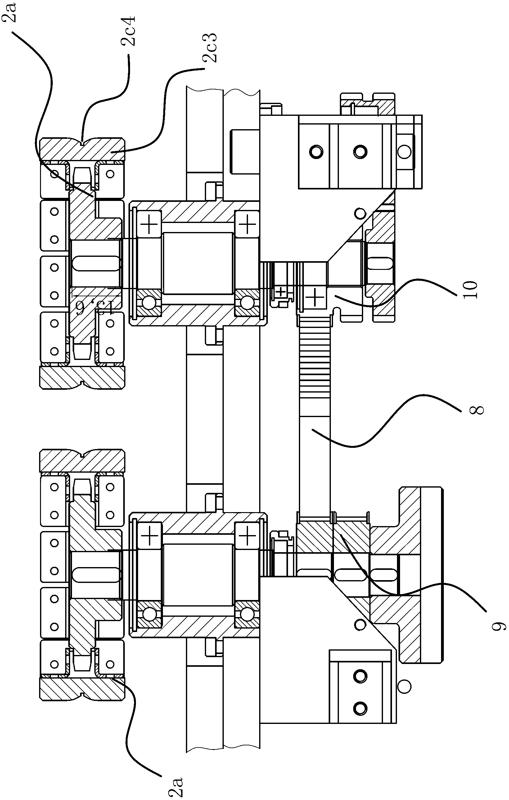
[0048] The structure of this embodiment is basically similar to that of the second embodiment. The difference is that the adjustment mechanism includes a first clamping cylinder 3, a set of conveyor track pairs 2 is provided with a first abutment member 5 inside the track 2c, and the other set of conveyor track pairs 2 A second abutment member 6 is provided on the inner side. The first abutment member 5, the second abutment member 6, the driving wheel 2a and the driven wheel 2b are all positioned on the frame 1 through corresponding guiding structures; the first clamping cylinder 3 The cylinder is connected with the first abutment member 5, and the piston rod is connected with the second abutment member 6.


PUM


Abstract

The invention provides a bar conveyer, belongs to the technical field of machining and solves the problem of insufficient and unstable clamping force of an existing crawler-type full-automatic bar feeding mechanism. The bar conveyer comprises a frame and two groups of conveyor crawler pairs, wherein the two groups of conveyer crawler pairs are oppositely arranged in parallel, and a bar clamping area is formed between the two groups of conveyer crawler pairs. Each group of the conveyor crawler pair comprises a driving wheel, a driven wheel and a crawler belt, and clamping grooves which are matched with a bar to be clamped are arranged on the surface of the crawler belt in the conveying direction of the bar. The machine frame is provided with a driving piece which can drives the driving wheel of at least one group of crawler pair to rotate. The conveyor crawler pairs are horizontally disposed and can limit and guide the bar from both sides of the bar on a horizontal plane, thereby improving the position accuracy when the bar is conveyed out.

Description

Technical field [0001] The invention belongs to the technical field of mechanical processing and relates to a bar feeder. Background technique [0002] At present, most of the cutting of metal bars is manually pushing the bars to the fixed-length backing of the cutting machine, and then punching and cutting. The existing automatic bar feeding mechanism that replaces manual work is based on the structure of a roller group. Specifically, a V-shaped groove or an arc groove is made on the outer circle of the feeding roller, and then a plurality of rollers are opposed to each other and clamped on both sides of the bar. For the bar, the motor drives the roller to push the bar to the cutting mechanism to cut it. Its structure has some shortcomings, mainly as follows: First, when the conveyed bar has a curved arc or the surface is oily, the rollers and the bar are prone to rolling and slipping, resulting in untimely or ineffective conveying; second, due to two phases There are distance...

Claims


Application Information

Patent Timeline
Patent Type & Authority Applications(China)
IPC IPC(8): B23Q7/03
Inventor 马文强
Owner 台州市良曜成套设备有限公司
Why Eureka
Try Eureka