
Flexible mechanical arm vibration reducing device and method based on controllable rigidity and controllable damp

A technology of flexible manipulator and vibration damping device, which is applied in manipulator, claw arm, vibration suppression adjustment, etc., can solve the problems such as the difficulty of implementing large-scale vibration control of flexible manipulator and the inability to make reasonable changes in the damping of vibration absorber, etc. Basic science and simple and feasible, simple structure, good effect

Inactive Publication Date: 2013-09-04
BEIHANG UNIV
View PDF8 Cites 37 Cited by
  • Summary
  • Abstract
  • Description
  • Claims
  • Application Information

AI Technical Summary

Problems solved by technology

For example, the marine magnetorheological elastomer intelligent shock absorber disclosed in the patent application number CN200910071707.0 and the magnetorheological elastomer frequency-shifting vibration absorber and control method disclosed in the patent application number CN200510094882.3 have great advantages in controlling the vibration of flexible structures. The effect is relatively good, but it will be difficult to implement the large-scale vibration control of the rigid-flexible flexible manipulator under the nominal motion, and the damping of the vibration absorber cannot be reasonably changed

Method used


Image

  • Flexible mechanical arm vibration reducing device and method based on controllable rigidity and controllable damp
  • Flexible mechanical arm vibration reducing device and method based on controllable rigidity and controllable damp
  • Flexible mechanical arm vibration reducing device and method based on controllable rigidity and controllable damp

Examples


Embodiment Construction

[0035] The present invention will be described in further detail below in conjunction with the accompanying drawings and specific examples, but the implementation of the present invention is not limited thereto.

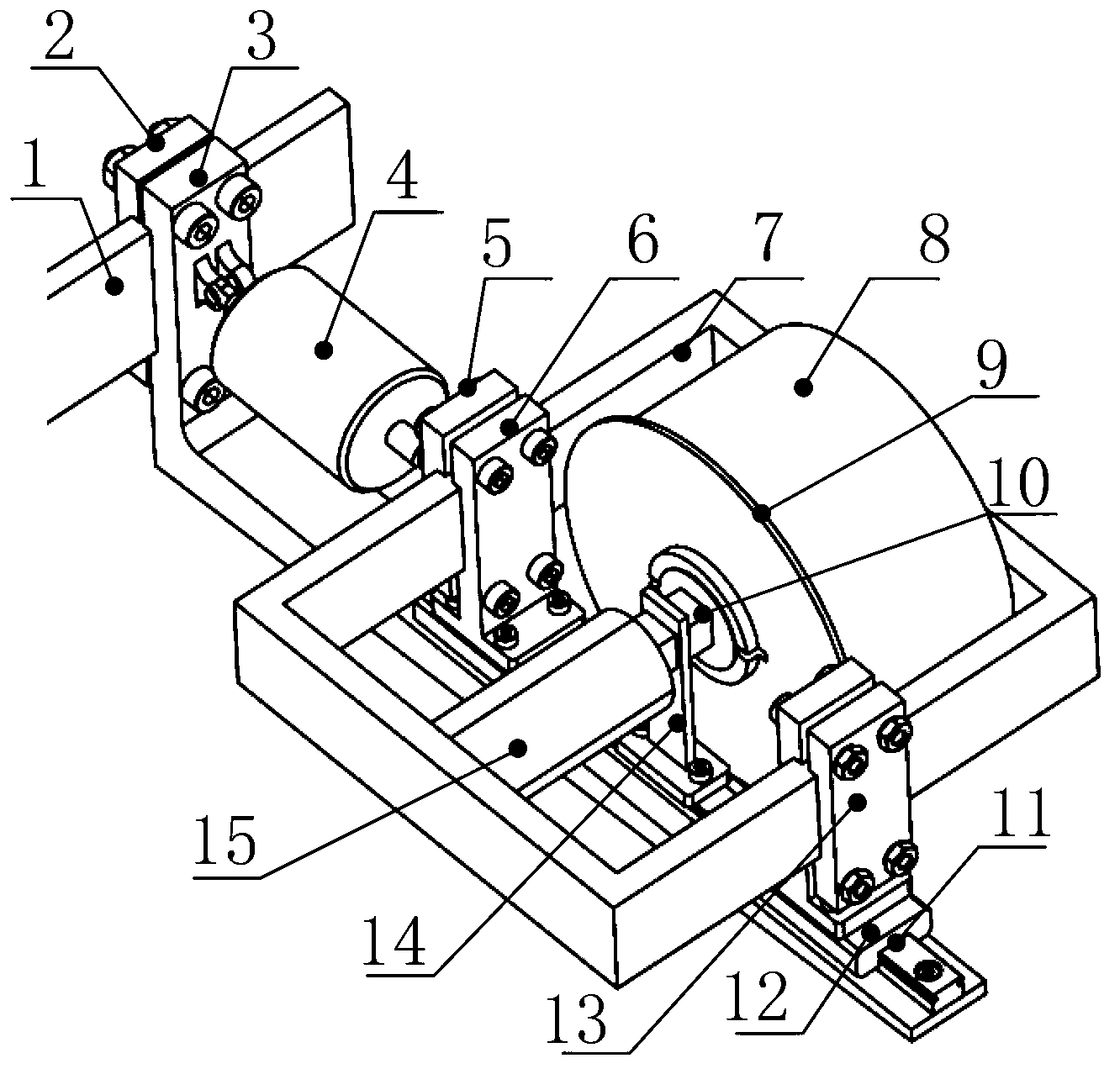
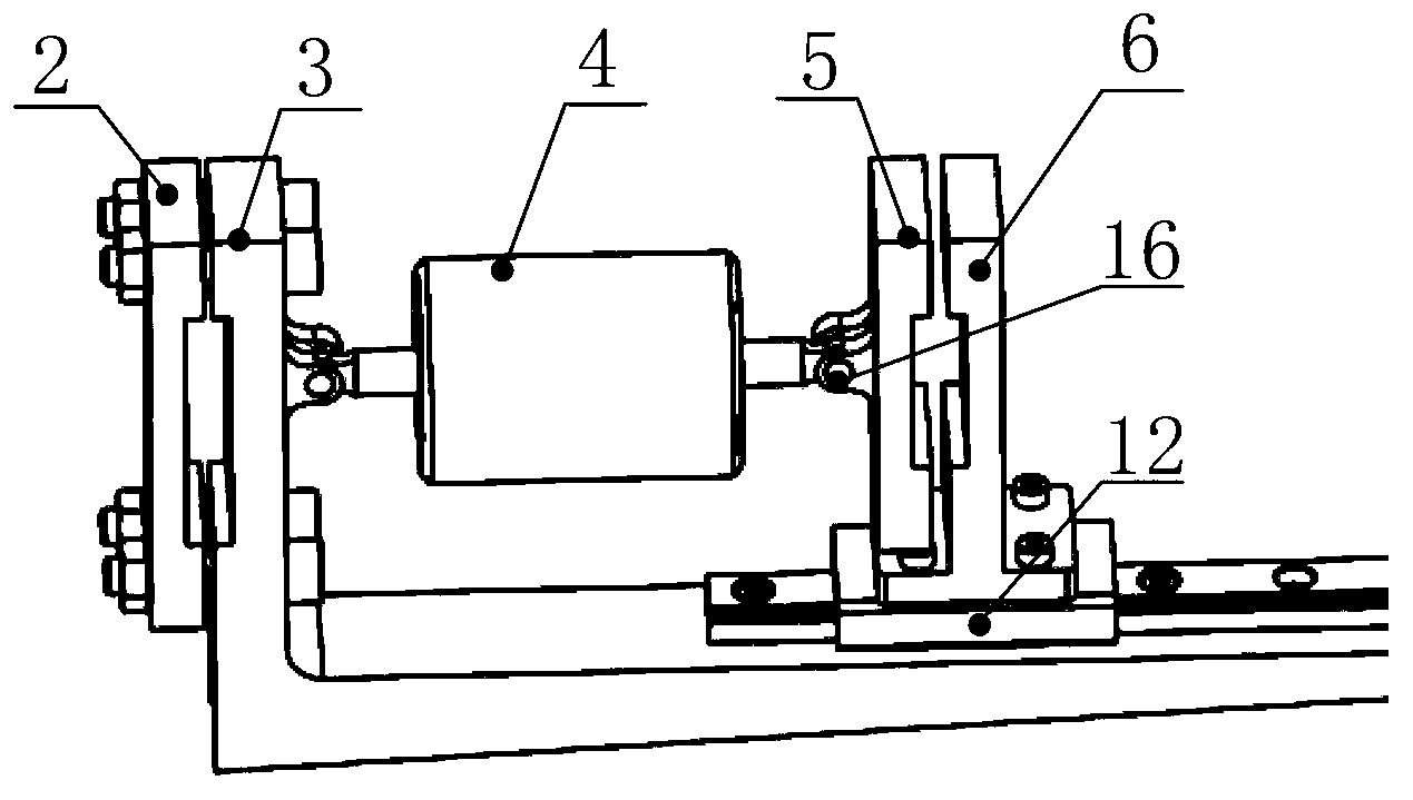
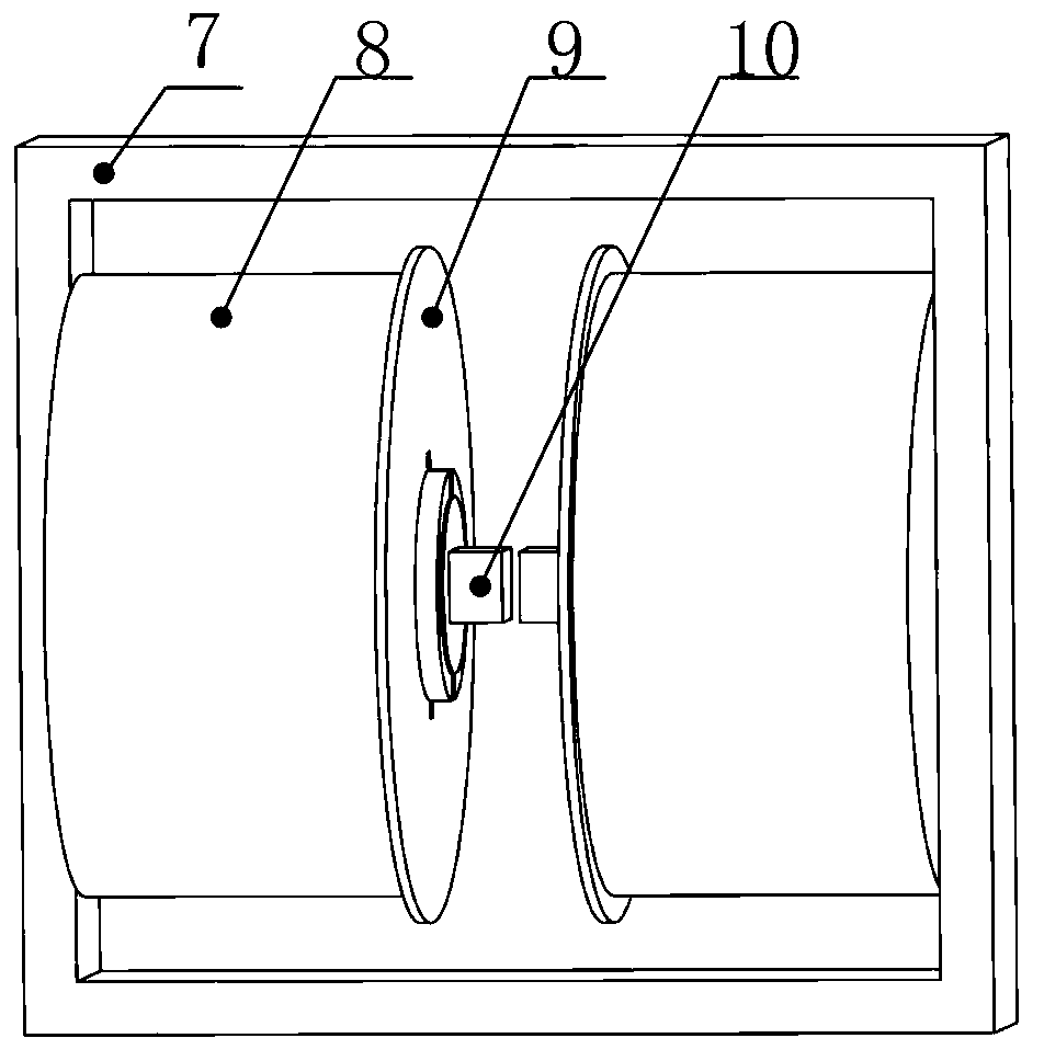
[0036] Such as figure 1 As shown, the present invention is based on a flexible manipulator vibration damping device with controllable stiffness and controllable damping, which is characterized in that it includes a flexible manipulator, a magneto-rheological damping device installed on the flexible manipulator and a linear guide rail for connection components, where:

[0037] The flexible manipulator 1 is the vibration control object. The magnetorheological damping device is composed of a magnetic circuit iron core 7, an excitation coil 8, a coil baffle 9, a magnetorheological elastomer 10 and a magnetorheological fluid damper 4. The linear guide rail assembly It is installed by flexible manipulator splint 2, guide rail installation beam 3, linear guide rail 11, sli...


PUM


Abstract

The invention relates to a flexible mechanical arm vibration reducing device and method based on controllable rigidity and controllable damp and belongs to the technical field of vibration control of flexible mechanical arms. The vibration reducing device comprises a flexible mechanical arm, a magneto-rheological vibration reducing device and a linear guide rail assembly playing a connecting role, wherein the flexible mechanical arm serves as a vibration control object, the magneto-rheological vibration reducing device consists of a magnetic circuit iron core, a magnet exciting coil, a coil blocking plate, a magneto-rheological elastic body and a magneto-rheological fluid damper, and the linear guide rail assembly consists of a flexible mechanical arm clamping plate, a guide rail installing beam, a linear guide rail, a sliding block, a magneto-rheological vibration reducing device clamping plate and an elastic body installing plate. The rigidity of the elastic body and the damp of the damper in the magneto-rheological vibration reducing device can be controlled by changing magnet exciting current, accordingly the requirement for internal resonance between the mechanical arm and the magneto-rheological vibration reducing device in a system is met, and vibration energy is consumed through the damper. The flexible mechanical arm vibration reducing device and method based on the controllable rigidity and the controllable damp has the advantages of being wide in vibration reducing frequency band and good in effect and being suitable for large-amplitude vibration reduction.

Description

technical field [0001] The present invention relates to a flexible manipulator vibration damping device and method based on controllable stiffness and controllable damping. The internal resonance phenomenon occurs in the system composed of the vibration device, and forms an energy exchange channel, and the vibration energy of the flexible manipulator is transferred to the vibration damping device and dissipated by the damping, which belongs to the technical fields of mechanical vibration, motion control of the flexible manipulator, etc. Background technique [0002] With the development of robot technology, the application of flexible manipulators with light weight, fast speed and high load-to-weight ratio has become a trend in industrial manufacturing and aerospace fields. Since the damping of the flexible manipulator is very small, the vibration will last for a long time and affect the normal work. Therefore, suppressing vibration and improving the operation accuracy of th...

Claims


Application Information

Patent Timeline
IPC IPC(8): B25J19/00B25J13/08B25J18/06F16F9/53
Inventor 高志慧邓玉春边宇枢
Owner BEIHANG UNIV
Learn More