
Preheating tank for heating sludge by steam

A preheating tank and steam technology, applied in the direction of sludge treatment through temperature control, can solve the problems of uneven heat exchange between sludge and steam, insufficient heat utilization, and low heat exchange efficiency of steam, so as to reduce sludge treatment Disposal costs, reduced heat loss, and reduced energy consumption

Inactive Publication Date: 2013-09-04
HUBEI GUOXIN TIANHUI ENERGY
View PDF8 Cites 0 Cited by
  • Summary
  • Abstract
  • Description
  • Claims
  • Application Information

AI Technical Summary

Problems solved by technology

[0003] The technical problem to be solved by the present invention is to provide a preheating tank device for raising the temperature of sludge to solve at least one of the following technical problems in the prior art: the heat exchange efficiency of steam caused by indirect heating of sludge by steam is low, and the heat The problem of insufficient utilization; the direct heating of steam to sludge causes uneven heat exchange between sludge and steam, and the problem that sludge is easy to scale and block steam pipes

Method used


Image

  • Preheating tank for heating sludge by steam
  • Preheating tank for heating sludge by steam
  • Preheating tank for heating sludge by steam

Examples


Embodiment Construction

[0025] The principles and features of the present invention are described below in conjunction with the accompanying drawings, and the examples given are only used to explain the present invention, and are not intended to limit the scope of the present invention.

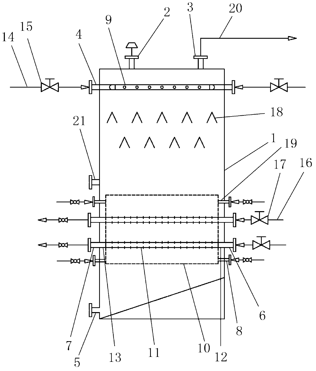
[0026] figure 1 It is a structural schematic diagram of the first embodiment of a preheating tank using steam to heat sludge in the present invention.

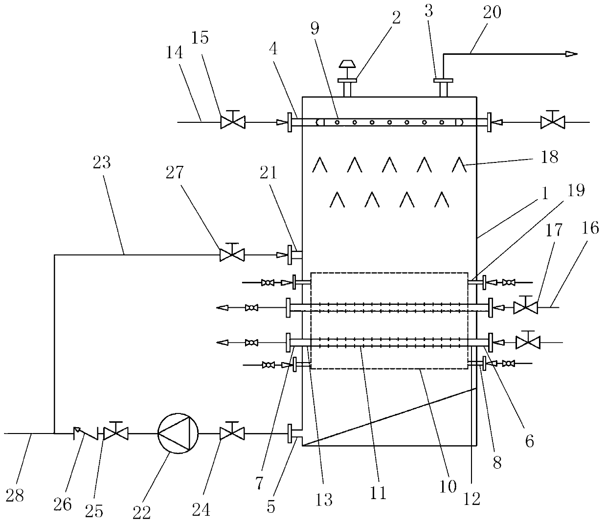
[0027] As shown in the figure, the preheating tank that uses steam to heat sludge includes a tank body 1, a breather valve 2 and an exhaust port 3 are provided on the top of the tank body 1, and a through hole is provided on the outside of the top side wall of the tank body 1. Through the mud inlet end 4 of the side wall of the tank body, the mud outlet end 5 passing through the side wall of the tank body is provided on the outside of the bottom side wall of the tank body 1, and the mud outlet end 5 passing through the side wall of the tank body 1 is also provided o...


PUM


Abstract

The invention relates to a preheating tank device for heating sludge, and belongs to the technical field of urban sewage and sludge treatment. A preheating tank for heating sludge by steam comprises a tank body, wherein the top of the tank body is provided with a breathing valve and an exhaust end; a sludge inlet end penetrating through the outer wall of the tank body is arranged on the side wall of the top of the tank body, and a sludge outlet end penetrating through the outer wall of the tank body is arranged on the side wall of the bottom of the tank body. A steam input end, a condensed water outlet end and a water cooler water-inlet end which penetrate through the outer wall of the tank body are also arranged on the side wall of the tank body, and a sludge distributing device, a water cooler and a steam distributing device are arranged in the tank body. The steam distributing device is arranged in the water cooler, the sludge distributing device is connected with the sludge inlet end, and the water cooler is connected with the water cooler water-inlet end. Through sludge preheating, the total time of subsequent thermal hydrolysis reaction is shortened, and the degree of thermal hydrolysis of sludge is increased. Through sludge distributing of the sludge distributing device, the heat exchange efficiency of sludge and steam can be increased, and the heat loss is reduced. The steam distributing device is protected by the water cooler to prevent the situation that the surface of the steam distributing device has sludge scaling to reduce the heat exchange efficiency of steam and sludge.

Description

technical field [0001] The invention belongs to the technical field of municipal sewage sludge treatment, and in particular relates to a preheating tank device for raising the temperature of sludge. Background technique [0002] Thermal hydrolysis technology is a pretreatment of sludge by using high-temperature and high-pressure steam to achieve cell wall breaking in sludge flocs, dissolution and hydrolysis of macromolecular organic matter, thereby improving the anaerobic digestion performance of sludge and the flow of sludge. A technology of sex. During the thermal hydrolysis process of sludge, a large amount of steam is often generated which cannot be fully utilized. In the prior art, steam is used to indirectly heat sludge, which often leads to low steam heat exchange efficiency and insufficient heat utilization; while using sludge and steam to directly exchange heat, there are uneven heat exchange between sludge and steam and sludge It is easy to foul and block the ste...

Claims


Application Information

Patent Timeline
IPC IPC(8): C02F11/18
Inventor 黄祥胜骆民强窦文龙
Owner HUBEI GUOXIN TIANHUI ENERGY
Learn More