

Semi-open impeller supercharge structure
A pressurized structure, semi-open technology, applied in non-variable pumps, engine cooling, liquid fuel engines, etc., can solve the problems of large water channel liquid resistance, increase the water outlet angle of impeller blades, etc., to improve water flow energy, increase the outlet angle, and improve the cooling effect
- Summary
- Abstract
- Description
- Claims
- Application Information
AI Technical Summary
Problems solved by technology
Method used
Image

Examples
Embodiment 1
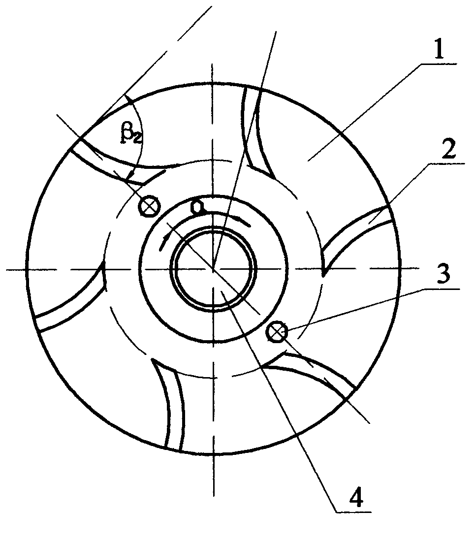
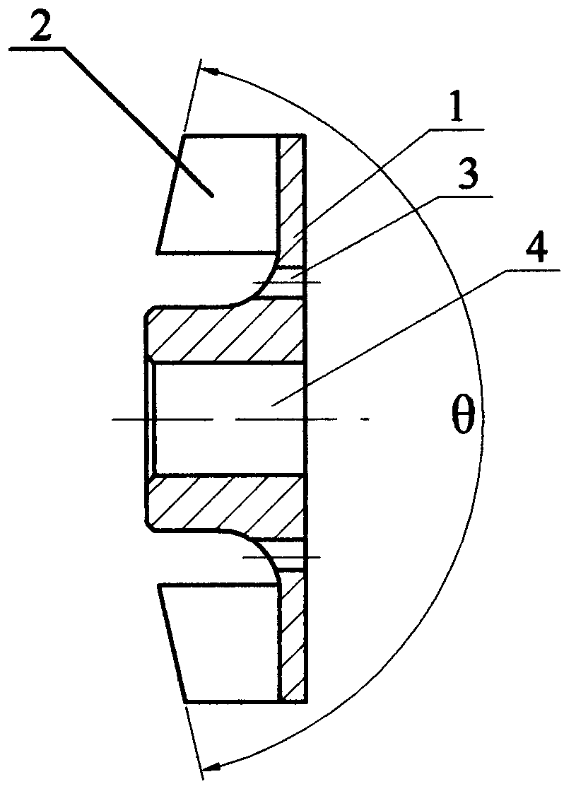
[0015] figure 1 The semi-open impeller supercharging structure shown is composed of back plate 1, blade 2, balance hole 3 and shaft hole 4. The back plate 1 in the impeller is a circular plate with a shaft hole 4 in the center, and a curved blade 2 is evenly distributed on the outer end surface according to the reverse rotation direction. The side of the blade 2 facing forward and concave is the working surface. The side that bulges backward is the back. In this embodiment, the diameter of the impeller is Φ70mm, and the top surface of the blade 2 is as image 3 It is conical as shown, and its cone angle θ=154°±3′. The top surface of the blade 2 adopts a conical shape, directly increasing the width of the blade near the suction port, which can improve the suction capacity of the impeller. The outlet angle of the blade 2 of the one-way arc surface body blade with backward design is as follows figure 1 All shown are β 2 =90°, the angle between the inner edges of the outlets o...
Embodiment 2
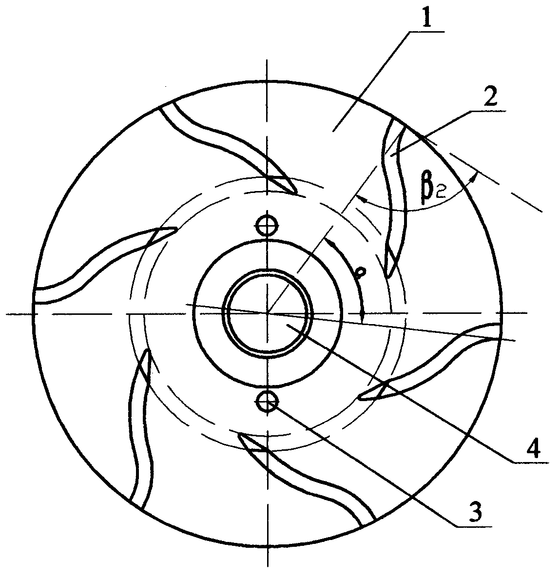
[0017] The present invention adjusts the design of the blades 2 in the impeller according to the specifications of the matching cooling water pump. In this embodiment, the diameter of the impeller is Φ100mm, first of all, it is evenly distributed on the outward end surface of the back plate 1 such as figure 2 The blade 2 shown is a two-way arc-shaped curved surface body that leans backward according to the reverse rotation direction, and the inner half and outer half of the blade 2 are reversely curved. Due to the shape change and lengthening of the blade 2, the ability to transport water is improved, so the outlet angle β of the blade 2 is adjusted 2 =70°, the cone angle θ=130° on the top surface of the blade 2, the angle between the inner edges of the outlets of the adjacent blades 2 on the outer circle of the impeller is α=60°, and the rest of the auxiliary parameters are unchanged. The impeller designed by adjusting the above parameters can achieve the application effect...
PUM
 Abstract
Description
Claims
Application Information