Optical lens

An optical lens and lens technology, applied in the field of optical lenses, can solve problems such as increasing design difficulty, excessive deviation, and affecting product uniformity, and achieve the effects of reducing design difficulty, reducing distance, and reducing light mixing distance

Active Publication Date: 2013-09-04
北京易美新创科技有限公司
View PDF4 Cites 25 Cited by
  • Summary
  • Abstract
  • Description
  • Claims
  • Application Information

AI Technical Summary

Problems solved by technology

[0006] 2) Due to the influence of the production and processing process, the free-form surface of the large-angle lens design may easily cause excessive deviation from the original design surface, which will affect the uniformity of the product
[0008] 4) The current large-angle diffusion lens design uses the refraction effect of the optical surface on the light to design the diffusion angle, which increases the design difficulty

Method used


Image

  • Optical lens
  • Optical lens
  • Optical lens

Examples


Embodiment 1

[0030] Apply optical lens to TV backlight

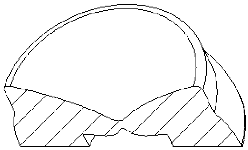
[0031] image 3 It is a cross-sectional view of the optical lens applied to the TV backlight module.

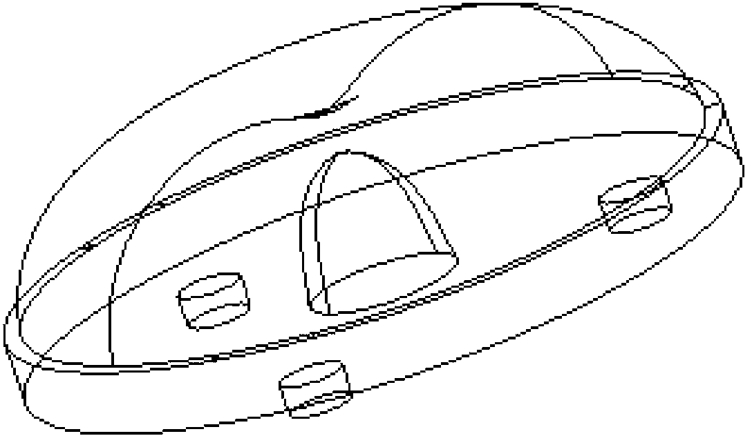
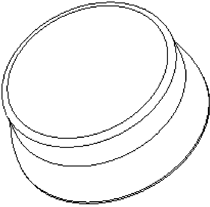
[0032] Figure 4 For this reason, the optical lens is applied to the structural diagram of the TV backlight module. The lens body 1 of the present invention is composed of a light-incident curved surface 12, at least two light-emitting curved surfaces, a bottom plane and a positioning pillar 40. The light-incident curved surface 12 formed at the bottom is a free-form surface with a center recessed upward; the light-emitting curved surface 15 formed at the top is a free-form curved surface with a center recessed downwards. The center of the light-incident curved surface 12 is recessed upwards and the center of the light exiting curved surface is recessed downwards The minimum thickness of the optical lens is 1mm, which is used to disperse the central light intensity of the LED point light source. The light-emitting curved surface 20 for...

Embodiment 2

[0036] Apply optical lens to panel light

[0037] Apply 25 pieces of this optical lens to 30w600mm x600mm panel light, 5x5 array, such as Figure 8 Shown.

[0038] The present invention has the following advantages:

[0039] 1) The present invention is formed into a shape with a thin center and thick edges, which facilitates the design of large-angle beams. The optical lens of the present invention needs to be used in conjunction with the bottom reflector. This design method can improve the light extraction efficiency of the optical lens;

[0040] 2) The light-emitting form of the present invention is refracted and matched with the reflective form. The light-emitting angle is above 270°, and the light beam above 180° is reflected by the reflective sheet placed at the bottom of the lens. It is applied to the backlight module and the refracted light is directly projected to the upper The bottom surface of the diffuser. The reflected light is emitted from the side edge of the lens, is ...


PUM


Abstract

The invention discloses an optical lens. The optical lens comprises a lens body. A light-incidence curved surface with the center sunk upwards for incidence of light is formed on the bottom of the lens body. A first light-exit curved surface with the center sunk downwards is formed on the top of the lens body. A second light-exit curved surface is formed on the side portion of the lens body. After incidence of the light through the lens body is finished, an included angle between the first light-exit curved surface and the axis of the lens body is 42 degrees as a critical angle, light beams between a central light beam and 42 degrees are refracted through the first light-exit curved surface, and light beams between 42 degrees and 85 degrees are refracted through the second light-exit curved surface after being totally refracted through the first light-exit curved surface. According to the optical lens, a catadioptric way is adopted for beam angle diffusion, and brightness uniformity on a receiving surface is improved.

Description

Technical field [0001] The invention relates to an optical lens, in particular to an optical lens applied to a direct type backlight system, belonging to the field of semiconductor lighting. Background technique [0002] As the secondary light distribution product of LED, optical lens is widely used in lighting field. Since this kind of optical lens is mostly composed of optical grade pmma (polymethyl methacrylate) or pc (polycarbonate) materials, it has the advantages of low cost, easy injection molding, high light transmittance, and small size, and is gradually being used To the field of LED backlight. [0003] Such as figure 1 As shown, the optical lens used in the LED backlight requires a large beam angle, generally between 155° and 160°. The light-emitting surface of the upper surface is a free-form surface; the lower surface is a flat surface, usually with prisms and cones. The light-incident surface facing the light source is composed of a non-conical surface. [0004] The ...

Claims


Application Information

Patent Timeline
Patent Type & Authority Applications(China)
IPC IPC(8): F21V5/04F21Y101/02
Inventor 朱贺玲刘国旭孙国喜
Owner 北京易美新创科技有限公司
Why Eureka
Try Eureka