Magnetic field sensor and Hall device

A magnetic field sensor and resistance element technology, applied in the field of measurement, can solve the problems such as the inability to apply the structure and preparation process of the semiconductor Hall resistance formation method, the inability to adjust the resistance value of the external resistance, and the lack of a better solution, which is beneficial to large The effect of large-scale industrialization promotion, wide measurement range and good linearity

Active Publication Date: 2013-09-04
INST OF PHYSICS - CHINESE ACAD OF SCI
View PDF9 Cites 7 Cited by
  • Summary
  • Abstract
  • Description
  • Claims
  • Application Information

AI Technical Summary

Problems solved by technology

Although the application achieves the balance of the bridge arm by adding an additional resistance inside the semiconductor potential well, the resistance value of the external resistance cannot be adjusted, and the ability to suppress the zero bias is limited
At the same time, the preparation process of the invention is complicated, and the formation method of the semiconductor Hall resistance cannot be applied to the Hall resistance based on the ferromagnetic film with a simpler structure and preparation process.
It can be seen that there is no better solution to the zero bias problem of the Hall device.

Method used


Image

  • Magnetic field sensor and Hall device
  • Magnetic field sensor and Hall device
  • Magnetic field sensor and Hall device

Examples


Embodiment Construction

[0029] In order to make the purpose, technical solutions and advantages of the embodiments of the present invention more clear, specific embodiments will be described in detail below with reference to the accompanying drawings.

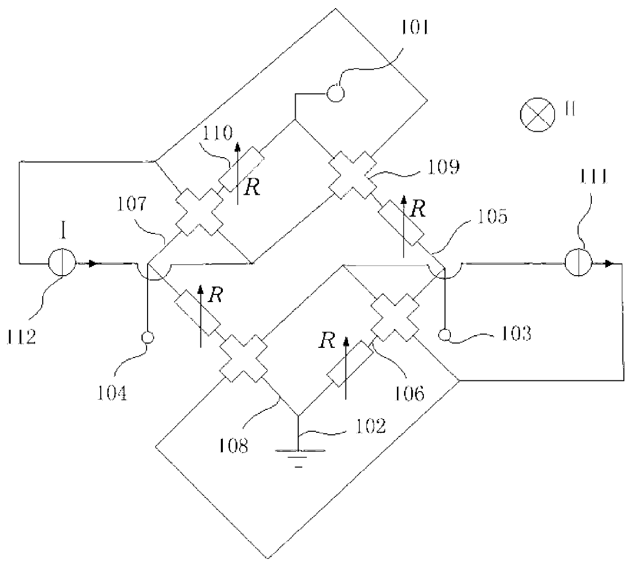
[0030] Such as figure 1 As shown, the magnetic field sensor may include a bridge circuit. The bridge circuit may include an excitation input terminal 101, a ground terminal 102, a first signal output terminal 103, a second signal output terminal 104, and four first bridge arms 105, second bridge arms 106, and fourth bridge arms connected in sequence end to end. Bridge arm 108, third bridge arm 107. Wherein, the excitation input terminal 101 is disposed between the first bridge arm 105 and the third bridge arm 107 , and the ground terminal 102 is disposed between the second bridge arm 106 and the fourth bridge arm 108 . The excitation voltage V can be applied to the bridge circuit through the excitation input terminal 101 and the ground terminal 102 ...


PUM


Abstract

The invention discloses a magnetic field sensor and a Hall device. The magnetic field sensor comprises a bridge circuit. The bridge circuit comprises four bridge arms. Each bridge arm comprises a Hall resistance element. At least one bridge arm also comprises an adjustable resistance element connected in series with the Hall resistance element on the corresponding bridge arm; each Hall resistance element is provided with a pair of resistance output ends and a pair of current input ends; the resistance output ends are connected to the interior of the corresponding bridge arm on which the Hall resistance element is located; and the current input ends are used for receiving working current so as to generate Hall resistance at the resistance output ends. According to the magnetic field sensor and the Hall device disclosed by the invention, the bridge circuit consists of the four Hall resistance elements and the adjustable resistance elements, and thus, bridge balance when no magnetic field exists can be realized. According to the magnetic field sensor and the Hall device disclosed by the invention, bridge differential output can be realized when a magnetic field exists, and therefore, the zero-field offset problem of the Hall device is greatly lowered structurally. The magnetic field sensor and the Hall device are simple in process and are in favor of large-scale industrialized popularization.

Description

technical field [0001] The invention relates to the measurement field, in particular to a magnetic field sensor and a Hall device that can be used in the magnetic field sensor. Background technique [0002] Semiconductor Hall resistors based on the Hall effect have the characteristics of good linearity, high sensitivity, and good stability. They have been widely used in the field of sensors to detect magnetic fields, currents, displacements, and rotational speeds. Compared with semiconductor Hall resistors, ferromagnetic alloys based on the anomalous Hall effect, such as CoPt alloys [see G.X.Miao and G.Xiao, Appl.Phys.Lett.85(2004)73], and magnetic metal multilayer films, Such as CoFe / Pt [see Chinese patent application 200610144053.6], etc., can also be used to prepare high-sensitivity Hall resistors, and has the advantages of simple preparation process and low cost. However, since the output of the anomalous Hall effect is related to the magnetism of the ferromagnetic mate...

Claims


Application Information

Patent Timeline
Patent Type & Authority Applications(China)
IPC IPC(8): G01R33/07
Inventor 吴少兵朱涛
Owner INST OF PHYSICS - CHINESE ACAD OF SCI
Why Eureka
Try Eureka