Flywheel energy storage system grid-connected control method and energy storage system thereof

A control method and flywheel energy storage technology, applied in the field of flywheel energy storage systems, can solve the problem of grid-connected charging and discharging power not being constant, etc.

Active Publication Date: 2013-09-04
INST OF ELECTRICAL ENG CHINESE ACAD OF SCI
View PDF7 Cites 39 Cited by
  • Summary
  • Abstract
  • Description
  • Claims
  • Application Information

AI Technical Summary

Problems solved by technology

[0006] In order to overcome the inconsistency of grid-connected charging and discharging power existing in the grid-connected control technology of the existing flywheel energy storage system, and the need to switch from the speed outer loop control to the voltage outer loop control in the control of the motor side converter when switching between grid-connected charging and discharging At the same time, in order to improve the grid-connected power factor of the flywheel energy storage system, the present invention proposes a grid-connected control method for the flywheel energy storage system, and a flywheel energy storage system using this control method

Method used


Image

  • Flywheel energy storage system grid-connected control method and energy storage system thereof
  • Flywheel energy storage system grid-connected control method and energy storage system thereof
  • Flywheel energy storage system grid-connected control method and energy storage system thereof

Examples


Embodiment Construction

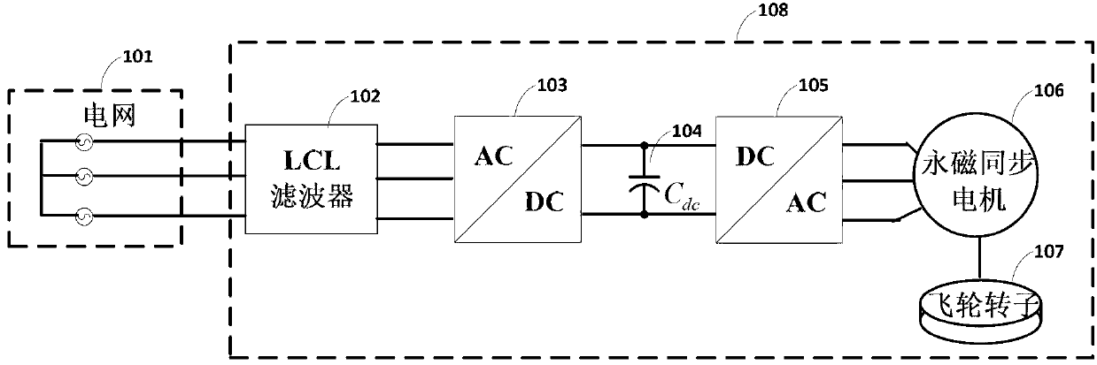
[0020] figure 1 It is a schematic diagram of grid connection of the flywheel energy storage system of the present invention. Such as figure 1 As shown, when the flywheel energy storage system 108 is connected to the grid for charging, the grid-side converter 103 rectifies the three-phase AC power into DC power, the motor-side converter 105 inverts the DC power into three-phase AC power, and the permanent magnet synchronous motor 106 works on the motor mode, the flywheel energy storage system 108 absorbs active power from the grid 101 . When the flywheel energy storage system 108 is grid-connected and discharged, the permanent magnet synchronous motor 106 works in generator mode, the motor-side converter 105 rectifies the three-phase AC power into DC power, and the grid-side converter 103 inverts the DC power into three-phase AC power, The flywheel energy storage system 108 provides active power to the grid.

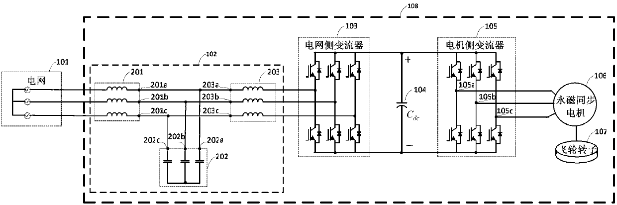
[0021] figure 2 It is the topological structure of the flywheel...


PUM


Abstract

The invention discloses a flywheel energy storage system grid-connected control method and an energy storage system thereof. A grid side converter control method of the flywheel energy storage system grid-connected control method comprises the following steps: converting grid side currents ia1, ib1 and ic1 and converter side currents ia2, ib2 and ic2 under a static coordinate system into direct current components id1 and iq1, and id2 and iq2 under a two-phase rotating coordinate system respectively; and taking the direct current components under the two-phase rotating coordinate system as feedback signals of grid side converter control under the rotating coordinate system to control the sizes and the flow directions of flywheel energy storage system grid-connected active power and passive power. A motor side converter control method of the flywheel energy storage system grid-connected control method comprises the following steps: converting motor stator currents ia3, ib3 and ic3 under the static coordinate system into direct current components id3, iq3 under the two-phase rotating coordinate system; and taking the id3, iq3 and direct current bus voltage Udc as feedback signals of motor side converter control under the rotating coordinate system to maintain constant direct current bus voltage Udc. An LCL filter (102) of the energy storage system applying the control method consists of a grid side inductor (201), a converter side inductor (203) and a filter capacitor (202).

Description

technical field [0001] The invention relates to a grid-connected control method of a flywheel energy storage system, in particular to a grid-connected control method of a flywheel energy storage system using an LCL filter and a back-to-back converter connected to the grid, and a flywheel energy storage system applying the control method. Background technique [0002] Flywheel energy storage stores energy in the form of mechanical energy in the high-speed rotating flywheel rotor. Due to its high power density, no environmental pollution, long service life, wide operating temperature range, and unlimited charge and discharge times, it is different from traditional chemical Compared with the battery, the advantages are obvious, and it has been widely concerned at home and abroad. The grid-connected operation of the flywheel energy storage system can actively adjust the active power of the grid, ensure the balance between supply and demand of the system, reduce the impact of act...

Claims


Application Information

Patent Timeline
Patent Type & Authority Applications(China)
IPC IPC(8): H02J3/38H02J3/30H02J3/18
CPCY02E40/30Y02E60/16
Inventor 刘文军唐西胜周龙齐智平
Owner INST OF ELECTRICAL ENG CHINESE ACAD OF SCI
Why Eureka
Try Eureka