Lathe center frame auxiliary clamping mechanism

An auxiliary clamping and center frame technology, which is applied in the direction of clamping, metal processing machinery parts, supports, etc., can solve the problems of unable to process the outer circle of the car, and the normal rotation of the moving bolts, etc., to achieve the effect of ensuring normal processing

Active Publication Date: 2013-09-11
宁波瑞亚紧固件制造有限公司
View PDF9 Cites 2 Cited by
  • Summary
  • Abstract
  • Description
  • Claims
  • Application Information

AI Technical Summary

Problems solved by technology

At present, although the lathe comes with a lathe center frame that plays a supporting role, when this type of lathe center frame supports the moving bolt, the multiple thimbles distributed on the lathe center frame according to the circumference are pressed against the outer circumferential surface of the moving bolt. In addition, when the lathe turns the outer circle of the moving bolt, the moving bolt rotates with the main shaft of the machine, so that the multiple thimbles on the stationary lathe steady frame and the outer peripheral surface of the moving bolt will tightly clamp the moving bolt. The bolt prevents the rotation of the moving bolt, which forms a state commonly known as a dead state in the industry, so that the moving bolt cannot rotate normally, and normal machining of the outer circle of the car cannot be performed.

Method used


Image

  • Lathe center frame auxiliary clamping mechanism
  • Lathe center frame auxiliary clamping mechanism
  • Lathe center frame auxiliary clamping mechanism

Examples


Embodiment Construction

[0020] The present invention will be further described below in conjunction with the accompanying drawings and specific embodiments.

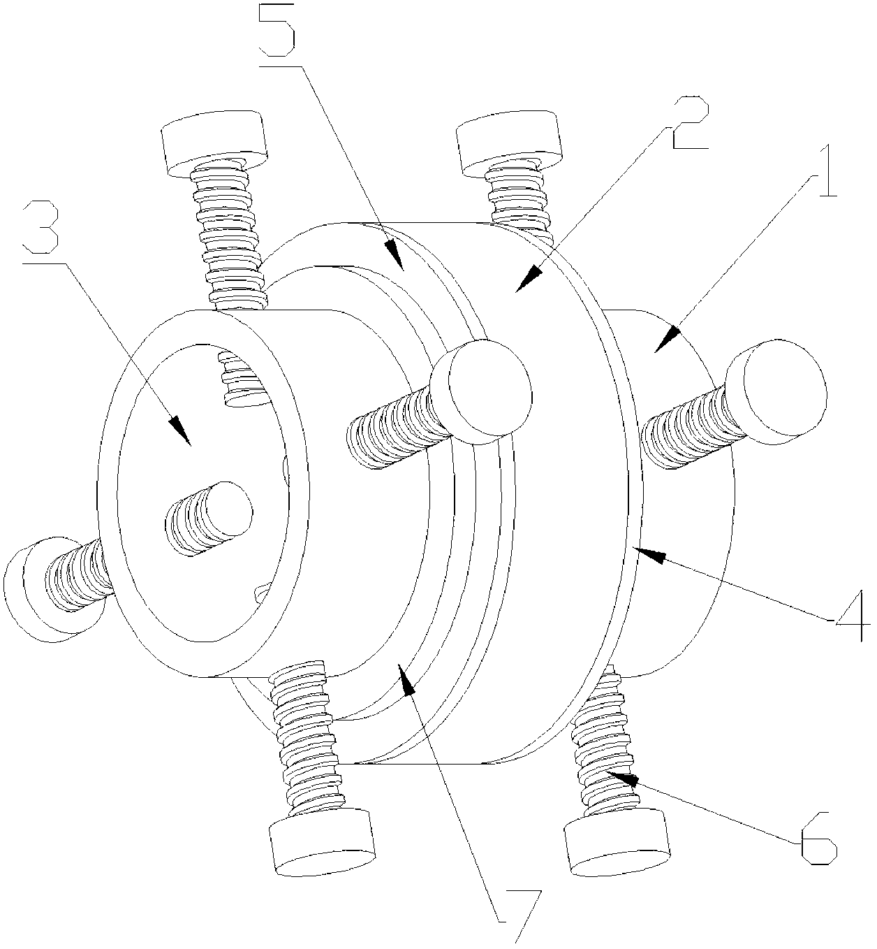
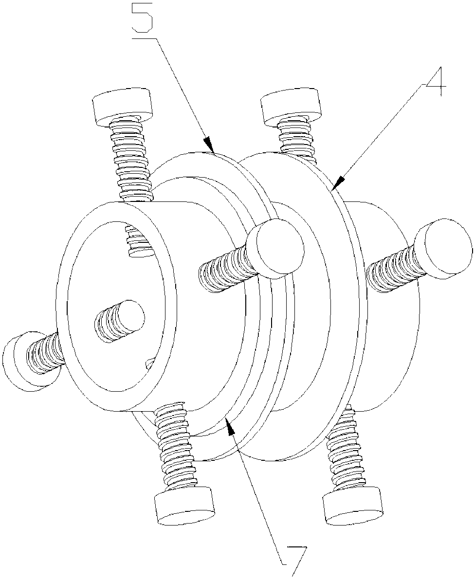
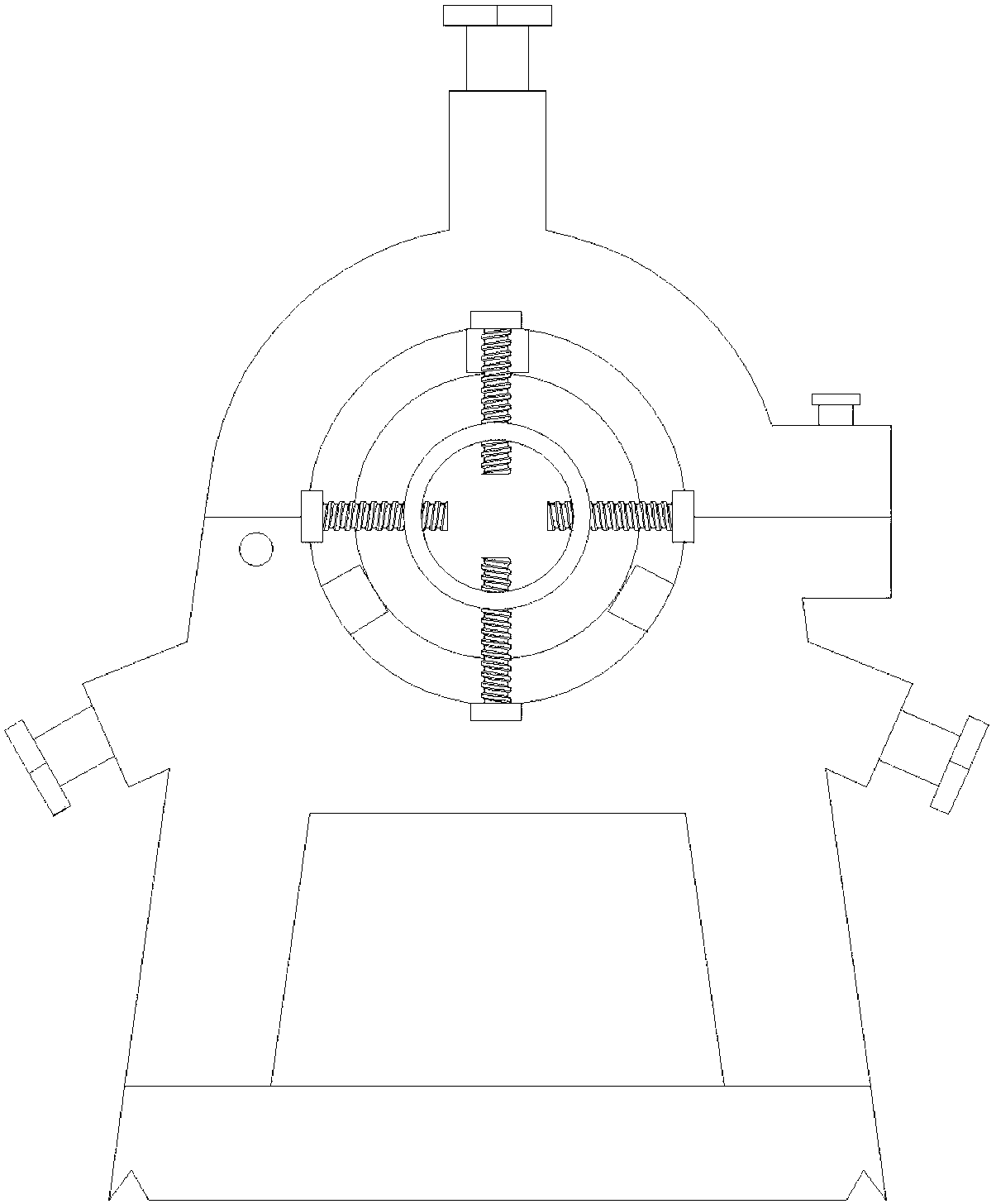
[0021] As shown in the figure, the auxiliary clamping mechanism of the lathe steady frame of the present invention includes a clamping sleeve 1 and a rolling bearing 2 . In this embodiment, the rolling bearing 2 is a ball bearing.

[0022] The clamping sleeve 1 is formed with a sleeve hole 3 for fitting the bolt to be processed, and the clamping sleeve 1 is provided with at least two compression rods 6 whose end faces press the outer circumference of the bolt to be processed. That is to say, the clamping sleeve 1 realizes synchronous rotation with the processed moving bolt by pressing the pressing rod 6 against the processed moving bolt. Of course, other structures can also be used to realize synchronous rotation, such as the way that the sleeve hole 3 is closely matched with the outer peripheral surface of the processed moving bolt to realize...


PUM


Abstract

The invention discloses a lathe center frame auxiliary clamping mechanism which comprises a clamping sleeve (1) and a rolling bearing (2), wherein a sleeve hole (3) used for installation of a machined moving bolt in a sleeved mode is formed in the clamping sleeve (1), the clamping sleeve (1) is at least provided with two pressing rods (6) with end faces pressing the outer circumferential face of the machined moving bolt, the rolling bearing (2) is axially installed on the clamping sleeve (1) in a limited mode, and the inner ring of the rolling bearing (2) is closely matched with the outer circumferential face of the clamping sleeve (1). The lathe center frame auxiliary clamping mechanism not only can support the machined moving bolt, but also enables the machined moving bolt to rotate, and can effectively guarantee lathing of the machined moving bolt.

Description

technical field [0001] The invention relates to an auxiliary clamping mechanism for the center frame of a lathe, in particular to an auxiliary clamping mechanism used on the center frame of the lathe when the outer circle of the moving bolts in the cylinder of the marine diesel engine is turned by a lathe. Background technique [0002] At present, there is a marine low-speed diesel engine with a tonnage of 1850t. The connecting parts used to connect the piston and the piston rod in the cylinder of the diesel engine are generally made of high-quality special alloy steel. The thread used, the connecting piece also moves together with the piston and piston rod while acting as a connection, so it is commonly called a sports bolt in the industry. [0003] Because the length of the moving bolt has reached a length of 10m, a support mechanism is required to support the moving bolt when the outer circle is turned on the lathe. At present, although the lathe comes with a lathe cente...

Claims


Application Information

Patent Timeline
Patent Type & Authority Applications(China)
IPC IPC(8): B23Q3/00B23Q1/76
Inventor 严统达
Owner 宁波瑞亚紧固件制造有限公司
Why Eureka
Try Eureka