Polishing device for high-temperature alloy inwards-protruding tube

A high-temperature alloy and polishing device technology, applied in the direction of grinding/polishing safety devices, surface polishing machine tools, grinding/polishing equipment, etc., can solve the problem of destroying the structure of the disturbance factor, affecting the performance of the furnace tube, and easily damaging the disturbance Factors and other issues, to achieve the effect of convenient use, improve the efficiency of grinding work, and improve the quality of grinding and polishing

Inactive Publication Date: 2013-09-11
江苏久保联实业有限公司
View PDF6 Cites 0 Cited by
  • Summary
  • Abstract
  • Description
  • Claims
  • Application Information

AI Technical Summary

Problems solved by technology

In the cracking furnace, most of the welding disturbance factors in the furnace tube are used to enhance heat transfer and inhibit coking. After the welding disturbance factor of the furnace tube, there will be welding slag and scale. In order not to affect the flow of the liquid in the tube, the resistance coefficient is reduced, and the melting The inner wall of the coated pipe needs to be polished. For the inner polishing of the slender inner wall, the use of electrolytic polishing will destroy the structure of the disturbance factor and affect the performance of the furnace tube; use a grinding head to polish, such as the steel pipe inner wall polishing machine disclosed in Patent No. 201020157282.3 , through the rotation and expansion of the grinding head into the steel pipe for polishing, but when the grinding head is polished, the heat is relatively large, which is easy to damage the inner wall of the tube and the disturbance factor on the inner wall, which also affects the performance of the furnace tube

Method used


Image

  • Polishing device for high-temperature alloy inwards-protruding tube

Examples


Embodiment Construction

[0016] The present invention will be further described below in conjunction with drawings and embodiments.

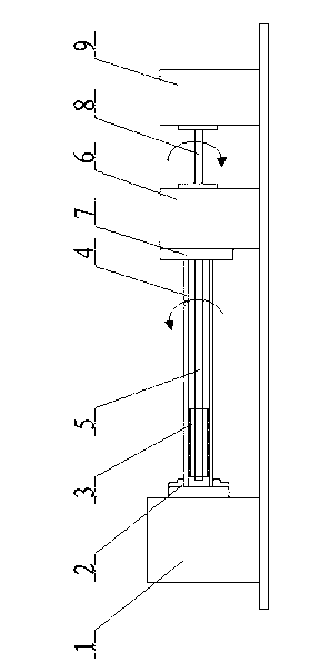
[0017] figure 1 As shown, a high-temperature alloy inner convex tube polishing device includes a rotating device 1 , an abrasive brush 3 , a connecting rod 5 , a cooling liquid delivery device 6 , a rotating rod 8 and an abrasive tool rotation driving device 9 . The rotating device 1 rotates and clamps one end of the high-temperature alloy inner convex tube 4 through the chuck 2, and the other end of the high-temperature alloy inner convex tube 4 is sealed and rotated on the top plate 7 of the coolant delivery device 6, and the coolant delivery device 6 passes through the top plate 7 It communicates with the superalloy inner convex tube 4, one end of the connecting rod 5 passes through the coolant delivery device 6 and connects to the rotary rod 8 of the abrasive rotary drive device 9, and the other end of the connecting rod 5 passes through the top plate 7 and is conne...


PUM


Abstract

The invention relates to a polishing device for a high-temperature alloy inwards-protruding tube. The polishing device comprises a rotating device, a grinding-tool rotation driving device, a connecting rod and a grinding tool. The rotating device is rotatably snapped at one end of the high-temperature alloy inwards-protruding tube, the grinding-tool rotation driving device is connected with one end of the connecting rod, a top plate is arranged on a coolant delivery device, the other end of the high-temperature alloy inwards-protruding tube is hermetically and rotatably supported on the top plate, the coolant delivery device is communicated with an inner cavity of the high-temperature alloy inwards-protruding tube through the top plate, one end of the connecting rod penetrates the coolant delivery device to be connected with a rotating rod of the grinding-tool rotation driving device, the other end of the connecting rod penetrates the top plate and the inner cavity of the high-temperature alloy inwards-protruding tube to be connected with the grinding tool. The coolant delivery device is adopted to rotatably support the high-temperature alloy inwards-protruding tube and grinding cooling is performed inside the high-temperature alloy inwards-protruding tube, so that requirements on polishing inside an elongated inwards-protruding tube are met, and the polishing device has the advantages of simple structure, convenience in use, high efficiency, long service life, good grinding quality and high accuracy.

Description

technical field [0001] The invention relates to a grinding device, in particular to a polishing device for the inner wall of a slender superalloy inner convex tube. [0002] Background technique [0003] At present, for the polishing of the inner wall of the slender tube at home and abroad, the methods with better polishing quality are electrolytic polishing and grinding head polishing. In the cracking furnace, most of the welding disturbance factors in the furnace tube are used to enhance heat transfer and inhibit coking. After the welding disturbance factor of the furnace tube, there will be welding slag and scale. In order not to affect the flow of the liquid in the tube, the resistance coefficient is reduced, and the melting The inner wall of the coated pipe needs to be polished. For the inner polishing of the slender inner wall, the use of electrolytic polishing will destroy the structure of the disturbance factor and affect the performance of the furnace tube; use a g...

Claims


Application Information

Patent Timeline
Patent Type & Authority Applications(China)
IPC IPC(8): B24B29/02B24B55/02
Inventor 李彬李雄
Owner 江苏久保联实业有限公司
Why Eureka
Try Eureka