Test tube cover removal device

A test tube cover and removal technology, applied in the field of medical devices, can solve the problems of low efficiency, sexual infection pollution, low degree of automation and low efficiency, and achieve the effect of simplifying the driving structure, ensuring synchronization, and improving operating efficiency

Inactive Publication Date: 2013-09-11
无锡特可思衡机贸易有限公司
View PDF7 Cites 13 Cited by
  • Summary
  • Abstract
  • Description
  • Claims
  • Application Information

AI Technical Summary

Problems solved by technology

[0002] After the collection of samples such as blood is completed, the test and analysis equipment must be used to detect and analyze the samples in the test tube. The sample needs to be opened before entering the test and analysis instrument. Among them, the manual opening method is inefficient and has potential hazards of contamination such as laboratory-acquired infection, while the machine automatic opening method has the characteristics of high efficiency and no pollution, but the existing machine automatic opening The tube racks applicable to the capping device are mostly custom-made rather than general-purpose tube racks, and the test tubes are uncapped one by one. The degree of automation and efficiency is not high. In the prior art, it is also possible to uncap multiple test tubes at the same time. However, they can only uncap the test tubes with the same diameter and the same length at the same time, but cannot simultaneously uncap the test tubes with the same diameter and different lengths.

Method used


Image

  • Test tube cover removal device
  • Test tube cover removal device
  • Test tube cover removal device

Examples


Embodiment Construction

[0042] The specific implementation manner of the present invention will be described below in conjunction with the accompanying drawings.

[0043] 1. The description of clamping lifting and cover opening mechanism 2 is as follows:

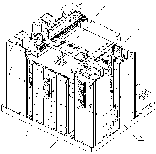
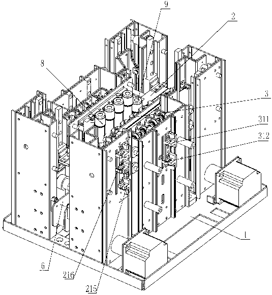
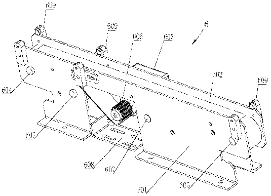
[0044] See Figure 4 , Figure 5 , Figure 6 , the clamping lifting and cover opening mechanism 2 includes a cover clamp 201 arranged horizontally, the cover clamp 201 can move up and down, and the two ends of the cover clamp 201 are fixedly connected with the sliders in the first linear guide rail pair 202 respectively, and the cover clamp Both ends of 201 are slidably supported on the cam mounting base 203 through the first linear guide pair 202. The cam mounting base 203 is equipped with a cam-204, and the other side of the cam-204 is provided with a cam guide with a guide slope-2051. Plate 1 205, cam 1 204 face guide slope 1 2051, cam guide plate 1 205 is slidably supported on frame 1 207 through second linear guide pair 206, frame 1 207 is ...


PUM


Abstract

A test tube cover removal device comprises a transverse clamping, lifting and cover-opening mechanism. A transverse mounting space and a longitudinal mounting space are formed between the clamping, lifting and cover-opening mechanism and a base. A clamping mechanism is mounted in the longitudinal mounting space, and the transverse mounting space transversely passes through the clamping mechanism. The clamping, lifting and cover-opening mechanism is provided with a transverse cover clamp which can move longitudinally and up and down. A cam is controlled to move by a cam guide plate having a guide slant, so that the cover clamp longitudinally moves to close or open. The cover clamp is driven to ascend and descend by an upper longitudinal telescoping arm of the am guide plate, a test tube cover is clamped by the cover clamp moving longitudinally, and the test tube cover is removed by the cover clamp moving up. The clamping mechanism is provided with a transverse test tube clamp; the cam is controlled to move by the cam guide plate having the guide slant, so that the test tube clamp opens or closes for clamping a test tube. The test tube cover removal device is available for opening covers of test tubes in batches, and available for opening covers of test tubes equal in diameter and different in length.

Description

technical field [0001] The invention relates to the technical field of medical devices, in particular to a device capable of automatically removing caps on test tubes containing samples such as blood. Background technique [0002] After the collection of samples such as blood is completed, the test and analysis equipment must be used to detect and analyze the samples in the test tube. The sample needs to be opened before entering the test and analysis instrument. Among them, the manual opening method is inefficient and has potential hazards of contamination such as laboratory-acquired infection, while the machine automatic opening method has the characteristics of high efficiency and no pollution, but the existing machine automatic opening The tube racks applicable to the capping device are mostly custom-made rather than general-purpose tube racks, and the test tubes are uncapped one by one. The degree of automation and efficiency is not high. In the prior art, it is also po...

Claims


Application Information

Patent Timeline
Patent Type & Authority Applications(China)
IPC IPC(8): B67B7/14
Inventor 施洪明倪冬亚
Owner 无锡特可思衡机贸易有限公司
Why Eureka
Try Eureka