Continuous membrane filtration system and water treatment method

A filter system and continuous membrane technology, applied in the direction of osmosis/dialysis water/sewage treatment, chemical instruments and methods, membrane technology, etc., can solve the problems of affecting the cost of water treatment, increasing the amount of chemical agents, increasing the cost, etc., to achieve Conducive to cleaning, reducing infrastructure costs and reducing usage

Active Publication Date: 2013-09-11
ZHEJIANG JINMO ENVIRONMENT TECH CO LTD
5 Cites 13 Cited by

AI-Extracted Technical Summary

Problems solved by technology

The increase in the amount of chemical agents will also increase the cost, and the cos...

Abstract

The invention discloses a continuous membrane filtration system and a water treatment method, and provides a continuous membrane filtration system for reducing the application amount of a chemical agent, and a water treatment method. A drug washing unit comprises a dosing pump and a drug washing pipeline, the outlet of the dosing pump is connected with the water inlet of a membrane module, one end of the drug washing pipeline is connected with the water outlet of the backwashing water tank of a backwashing unit, the other end of the drug washing pipeline is connected with the inlet of the water inlet pump of a water inlet unit, and the drug washing pipeline is provided with a diversion regulating valve and a diversion valve; one end of a produced water return valve is connected with the return port of the membrane module, and the other end of the produced water return valve is connected with the water production port of the membrane module and the water supplementing port of the backwashing water tank of the backwashing unit respectively; and one end of a regulating pipeline is connected with the inlet of the water inlet pump of the water inlet unit, the other end of the regulating pipeline is connected with the inlet port of the discharge valve of a return unit, and the regulating pipeline is provided with a filtering mode regulating valve used for selecting a cross flow filtering mode or a dead filtering mode. The system increases the filtering and cleaning flexibility and saves the application amount of the chemical agent.

Application Domain

Technology Topic

Produced waterChemical agents +8

Image

  • Continuous membrane filtration system and water treatment method

Examples

  • Experimental program(1)

Example Embodiment

[0028] The present invention will be further described in detail below in conjunction with the drawings and specific embodiments.
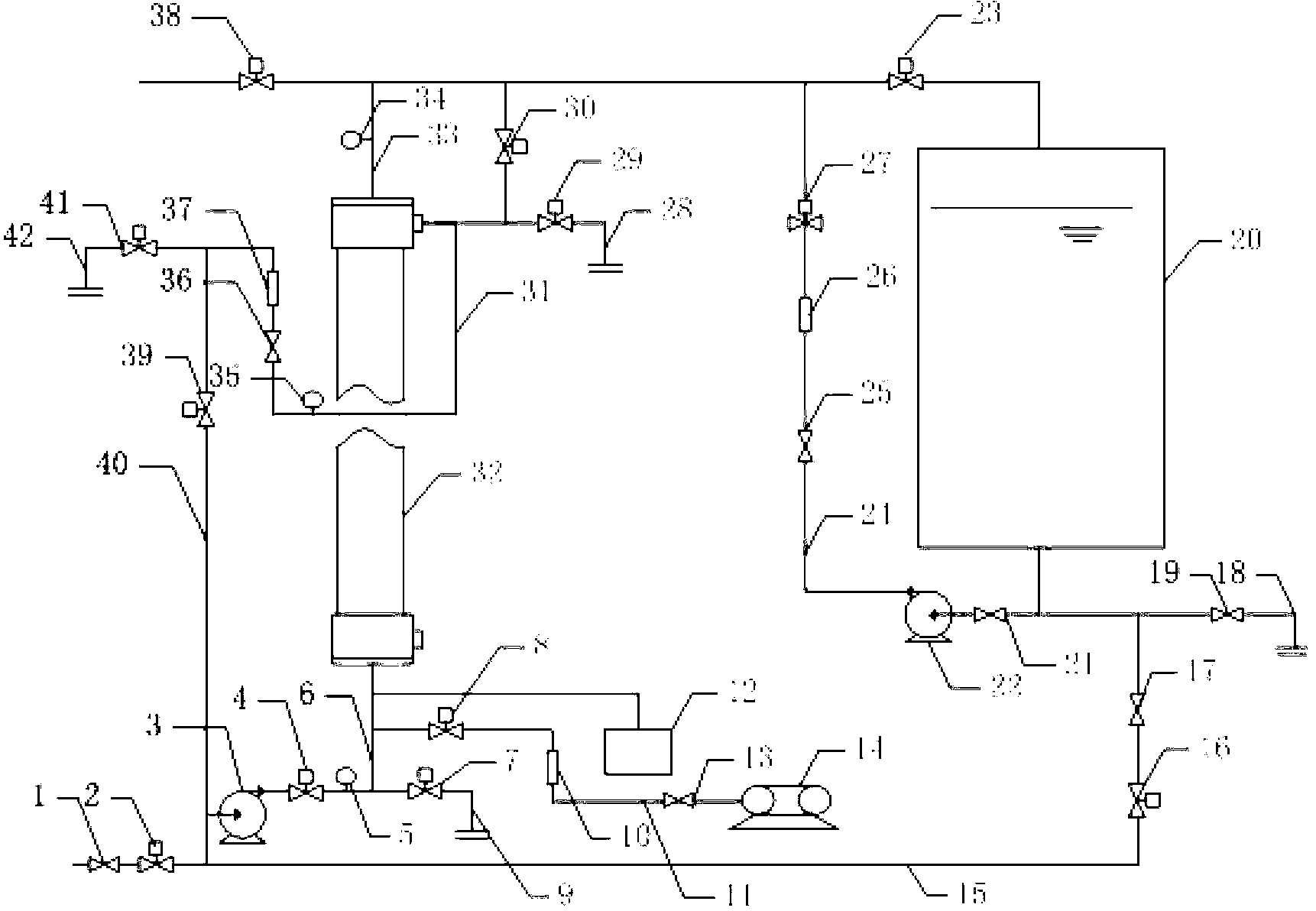
[0029] The schematic diagram of the continuous membrane filtration system of the present invention is as figure 1 As shown, it includes a membrane module 32, a water inlet unit, an aeration unit, a water production unit, a backwash unit, a backflow unit, a module upper discharge valve 29 and a module lower discharge valve 7, and the water inlet of the membrane module 32 is connected The lower module discharge valve 7, the outlet of the lower module discharge valve 7 is connected to the lower discharge pipe 9 of the module, the backflow port of the membrane module 32 is connected with the upper module discharge valve 29, and the upper module discharge valve The outlet of 29 is connected to the discharge pipe 28 on the assembly. It also includes a product water return valve 30, a regulating unit, and a medicine washing unit. The medicine washing unit includes a medicine dosing pump 12 and a medicine washing pipeline 15. The outlet of the medicine pump 12 is connected to the water inlet of the membrane module 32 One end of the medical washing pipeline 15 is connected with the outlet of the backwash water tank 20 of the backwash unit, and the other end is connected with the inlet of the water inlet pump 3 of the water inlet unit. The medical washing pipeline 15 is installed Water diversion regulating valve 17 and water diversion valve 16. One end of the product water return valve 30 is connected with the return port of the membrane module 32, and the other end is respectively connected with the water production port of the membrane module 32 and the water supply port of the backwash water tank 20 of the backwash unit. The regulating unit includes a regulating pipe 40, one end of the regulating pipe 40 is connected to the inlet of the water inlet pump 3 of the water inlet unit, and the other end is connected to the inlet end of the discharge valve 41 of the backflow unit. A filter mode regulating valve 39 for selecting cross-flow mode filtration or dead-end filtration mode is installed on the road 40. The function of the adjustment pipeline is to empty the air in the adjustment pipeline during cross-flow filtration, so that part of the influent water can return to the front of the water inlet pump, and then enter the membrane module together with the incoming water; the second is to cross-flow during chemical washing Exhaust by filtration, then let the medicine circulate continuously through the water inlet pipeline, membrane module, production water pipeline, production water return valve, return pipeline, regulating pipeline, and then the inlet pipeline.
[0030] The backflow unit includes a backflow pipe 31, a backflow regulating valve 36, a backflow flow meter 37, a backflow pressure gauge 35, a discharge valve 41, and a discharge pipe 42. One end of the backflow pipe 31 is connected to the backflow port of the membrane module 32. The other end is connected with the inlet of the discharge valve 41, and the outlet of the discharge valve 41 is connected with the discharge pipeline 42. The return flow pipe 31 is provided with the return flow regulating valve 36, the return pressure gauge 35 and the return flow meter 37.
[0031] The water inlet unit includes a water inlet pipe 6, a water inlet regulating valve 1, a water inlet valve 2, the water inlet pump 3, a water inlet valve 4, and a water inlet pressure gauge 5. The water inlet pipe 6 is connected to the The water inlet of the membrane module 32 is connected, the water inlet pump 3 is installed on the water inlet pipe 6, and the water inlet regulating valve 1 and the water inlet valve 2 are installed on the water inlet pipe before the water inlet pump 3. The water inlet valve 4 and the water inlet pressure gauge 5 are installed on the water inlet pipe behind the water inlet pump 3.
[0032] The backwash unit includes a backwash pump 22, a backwash pipeline 24, a backwash pump front valve 21, a backwash pump rear valve 25, a backwash flow meter 26, a backwash valve 27, a backwash make-up valve 23, the Backwash water tank 20, backwash lower drain valve 19 and backwash lower drain pipe 18. One end of said backwash pipe 24 is connected with the outlet of said backwash water tank 20, and the other end is connected with the production of said membrane module 32. The water port is connected to the produced water return valve 30, the backwash water makeup valve 23 is installed between the water production port of the membrane module 32 and the water replenishment port of the backwash water tank 20, and the backwash pipeline 24 is installed There is the backwash pump 22, the backwash pump front valve 21 is installed on the backwash pipeline before the backwash pump 22, and the backwash pump is installed on the backwash pipeline after the backwash pump 22 After the valve 25, the backwash flow meter 26 and the backwash valve 27, the backwash lower drain valve 19 is connected to the outlet of the backwash water tank 20, and the outlet of the backwash lower drain valve 19 is connected to the reverse Wash down the drain pipe 18 connection.
[0033] The water production unit includes a production water pipeline 33, a production water valve 38, and a production water pressure gauge 34. The production water pipeline 33 is connected to the water production port of the membrane module 32, and the water production pipeline 33 is installed Production water pressure gauge 34 and production water valve 38.
[0034] The aeration unit includes an air compressor 14, an aeration pipe 11, an aeration regulating valve 13, an aeration flow meter 10, and an aeration valve 8. The air outlet of the air compressor 14 passes through the aeration pipe 11 is connected to the water inlet of the membrane module 32, and the aeration regulating valve 13, the aeration flow meter 10 and the aeration valve 8 are installed on the aeration pipeline 11.
[0035] In the water treatment method of the present invention, the water production process and the physical cleaning process are the same as the prior art, but the difference lies in the chemical cleaning process. Chemical cleaning is carried out after a certain period of water production and physical cleaning. The chemical cleaning process of the present invention includes the following steps:
[0036] (1) Empty the solution in the membrane module.
[0037] (2) The clean water is continuously introduced into the membrane module from the backwash water tank.
[0038] (3) Under a certain pressure, make the clean water continuous in the medicine washing pipeline, the inlet pipeline after the inlet pump, the membrane module, the production water return valve and the pipeline between the production water outlet, the return pipeline, and the regulating pipeline The pressure during cleaning is determined according to the cleaning needs according to the routine.
[0039] (4) After the exhaust is finished, stop the introduction of clean water, discharge the same volume of clean water as the dosage, and then stop the discharge and close the water inlet pump to do the medicine. After adding the medicine, make the prepared cleaning liquid circulate continuously in the inlet pipe, membrane module, product water return valve and the pipeline between the water production port, return pipeline, and regulating pipeline after the water inlet pump, to perform the membrane module Medicine wash
[0040] (5) After the medicine washing cycle, let it stand for soaking or backwashing to end the washing process.
[0041] use figure 1 The specific process of the continuous membrane filtration system of the present invention for water treatment is as follows:
[0042] Before filtration, the filtration mode is adjusted by the filtration mode adjustment valve 39. When low energy consumption is the main indicator, dead-end filtration is used, and when the dead-end filtration method is adopted, the filter mode adjustment valve 39 is closed; when the main indicator is to reduce membrane pollution, cross-flow filtration is adopted, and when the cross-flow filtration method is adopted, the filtration mode is opened to adjust Valve 39.
[0043] 1. Exhaust: In order to prevent the influence of the gas in the membrane module and various pipes, exhaust first.
[0044] Only the water inlet regulating valve 1, the before water inlet valve 2, the after water inlet valve 4, the backwash water make-up valve 23 or the water production valve 38, the backflow regulating valve 36 and the discharge valve 41 are opened. Turn on the water inlet pump 3, when the dead-end filtration method is used for exhaust, the raw water flows from the water inlet regulating valve 1, the water inlet valve 2, the water inlet pump 3, the water inlet valve 4, the water inlet pressure gauge 5, and the water inlet of the membrane module 32 Enter the membrane module 32, and then flow out from the return port of the membrane module 32, flow through the return pressure gauge 35, the return control valve 36, the return flow meter 37, and the discharge valve 41 from the discharge pipe 42 to empty the membrane module and the water inlet pipe The gas in the return line and the return line; when the cross-flow filtration method is selected for exhaust, the filtration mode regulating valve 39 is opened, and the raw water flows from the water inlet regulating valve 1, the water inlet valve 2, the water inlet pump 3, and the water inlet valve 4, The water inlet pressure gauge 5 and the water inlet of the membrane module 32 enter the membrane module 32, and then flow out from the return port of the membrane module 32, pass through the return pressure gauge 35, the return valve 36, and the return flow meter 37, and then divide into two paths, one path The raw water with gas flows out from the discharge pipe 42 through the discharge valve 41, and the air is discharged. The other raw water with gas passes through the filter mode regulating valve 39 and the regulating pipe 40 and is again pumped into the membrane module by the inlet pump along with the inlet water. . Repeat the above-mentioned circulation process continuously to empty the gas in the membrane module, water inlet pipe, return pipe and regulating pipe.
[0045] Therefore, the exhaust time of cross-flow filtration is longer than that of dead-end filtration.
[0046] 2. Water production: After the gas is emptied, close the discharge valve 41, and then open the backwash water make-up valve 23 for normal water production.
[0047] When the dead-end filtration method is adopted, the raw water entering the membrane module 32 enters the water production pipeline 33 through the filtration of the hollow fiber membrane filaments, and then enters the backwash water tank 20 through the backwash water supplement valve 23. When the backwash water tank 20 stores enough water, the backwash water make-up valve 23 is closed, the water production valve 38 is opened, and the dead-end filtration and water production are continued.
[0048] When the cross-flow filtration mode is selected, part of the raw water entering the membrane module 32 is filtered by the hollow fiber membrane filaments, enters the hollow fiber membrane filaments from the outside of the hollow fiber membrane filaments, and then enters the water production pipeline 33, and the produced water passes through the reactor. The wash and make-up water valve 23 enters the backwash water tank 20, and another part of the raw water in the membrane module flows directly into the return line 31 from the return port of the membrane module, and passes through the return pressure gauge 35, the return control valve 36, the return flow meter 37, and the filter mode control valve. 39. The regulating pipeline 40 is pumped into the membrane module by the inlet pump along with the inlet water. When the backwash water tank 20 stores enough water, the backwash water make-up valve 23 is closed, the water production valve 38 is opened, and the cross-flow filtration water production is continued.
[0049] 3. Physical cleaning: when the water is produced for a certain period of time, close the water inlet regulating valve 1, the before water inlet valve 2, the water inlet pump 3, the after water inlet valve 4, the product water return valve 30, the filter mode regulating valve 39, and the backwash water supply Valve 23 or water production valve 38, open the upper discharge valve 29 of the module and the lower discharge valve 7 of the module to discharge the lowered liquid level, so that the water level in the membrane module is continuously reduced to a certain liquid level, generally less than half of the membrane module, preferably lower After reaching the one-quarter position, close the lower discharge valve 7 of the assembly, open the aeration valve 8, the aeration regulating valve 13, the air compressor 14 in the aeration unit, and the backwash pump front valve 21, Backwash pump 22, backwash pump back valve 25, backwash valve 27, backwash water in backwash water tank 20 passes through backwash pump front valve 21, backwash pump 22, backwash pump rear valve 25, and backwash flowmeter 26. The backwash valve 27 and the water production pipeline 33 enter the hollow fiber membrane filaments, and the gas generated by the air compressor 14 enters the hollow fiber membrane in the membrane module through the aeration regulating valve 13, the aeration flow meter 10, and the aeration valve 8. The outside of the silk is physically cleaned by backwashing and aeration. The cleaned sewage enters the upper discharge valve 29 of the assembly and is discharged through the upper discharge pipeline 28 of the assembly.
[0050] After physical cleaning for a certain period of time, close the aeration valve 8, aeration regulating valve 13, air compressor 14, and the backwash pump front valve 21, backwash pump 22, and backwash pump rear valve 25 of the backwash unit , Backwash valve 27, open the lower discharge valve 7 of the module, the liquid in the membrane module is emptied through the lower discharge pipeline 9 of the module and then reproduces the water step.
[0051] 4. Chemical cleaning: chemical cleaning is carried out after a certain period of water production and physical cleaning. First, open the upper discharge valve 29 and the lower discharge valve 7 of the module to drain the liquid in the membrane module. After that, close the upper discharge valve 29 and the lower discharge valve 7 of the component, open the water diversion regulating valve 17, the water diversion valve 16, the product water return valve 30, the post-intake valve 4, the return control valve 36, the discharge valve 41, and the water inlet pump 3 , The clean water is introduced into the membrane module, and the exhaust is performed by cross-flow filtration by opening the filtration mode regulating valve 39. Water enters the membrane module 32 from the backwash water tank 20 through the water diversion regulating valve 17, the water diversion valve 16, the water inlet pump 3, the water inlet valve 4, the water inlet pressure gauge 5, and the water inlet of the membrane module 32. The water flowing out of the nozzle enters the return line 31 through the product water return valve 30, flows through the return pressure gauge 35, the return control valve 36, and the return flow meter 37, one way flows out of the discharge pipe 42 through the discharge valve 41, and the other is filtered The regulating valve 39 and the regulating pipeline 40 enter the membrane module together with the inlet water, and after continuous circulation, the gas in the membrane module and the water production pipeline, the return pipeline and the regulating pipeline are emptied.
[0052] After the gas is emptied, close the water diversion regulating valve 17 and the water diversion electric valve 16. After a certain period of time is allowed to discharge clean water with a volume equivalent to the dosing volume, close the discharge solenoid valve 40, the water inlet pump 3, and open the upper discharge valve 29 and the dosing pump 12. The medicinal solution directly enters the membrane module through the inlet of the membrane module. After a sufficient amount of chemical agent is injected, the upper discharge valve 29 and the dosing pump 12 are closed, and the water inlet pump 3 is turned on to keep the cleaning solution with chemical agent in The membrane module circulates in the pipeline, that is, part of the cleaning solution in the membrane module flows from the outside of the membrane filament, through the inside of the membrane, from the water production port, and flows back to the return line 31 through the production water return valve 30, and the other part of the cleaning solution is directly from the membrane filament The outside flows into the return line 31 from the return port of the membrane module, merges with the cleaning solution flowing out of the product water return valve, and passes through the return pressure gauge 35, the return control valve 36, the return flow meter 37, the filter mode control valve 39, the control pipeline 40, The water inlet pump 3, the water inlet valve 4, and the water inlet pressure gauge 5 re-enter the membrane module for circulation. After circulating for a certain period of time, close all valves for soaking, or directly close all valves and open the upper discharge valve 29 and lower discharge valve 7 of the module to discharge the cleaning solution in the membrane module. After a certain period of time, the membrane module should be cleaned according to the manufacturer’s needs. Backwash or air-water mixed cleaning. If the cleaning requirements cannot be met, repeat the above chemical cleaning steps for a second chemical cleaning. If the cleaning requirements are met, proceed to the normal water production process.

PUM

no PUM

Description & Claims & Application Information

We can also present the details of the Description, Claims and Application information to help users get a comprehensive understanding of the technical details of the patent, such as background art, summary of invention, brief description of drawings, description of embodiments, and other original content. On the other hand, users can also determine the specific scope of protection of the technology through the list of claims; as well as understand the changes in the life cycle of the technology with the presentation of the patent timeline. Login to view more.

Similar technology patents

Battery level indication by portable telephone

InactiveUS20120190305A1Reduce usageWireless architecture usageElectrical testingState of chargeHuman–machine interface
Owner:STMICROELECTRONICS SRL

Seal arrangement

Owner:ROLLS ROYCE PLC

Classification and recommendation of technical efficacy words

  • Low cost
  • Reduce usage

Semiconductor device

InactiveUS6975142B2Low costReduce manufacturing stepsTransistorSolid-state devicesVoltage amplitudeSemiconductor
Owner:SEMICON ENERGY LAB CO LTD

System and method of model-driven development using a transformation model

InactiveUS20060064667A1Reducing model complexityReduce usageModel driven codeSpecific program execution arrangementsModel driven developmentGraphical model
Owner:FREITAS JOSE DE

Telecommunications networks and devices

InactiveUS20110263274A1Reduce usageNeed can be usedAssess restrictionNetwork topologiesBroadband connectionBase station
Owner:VODAFONE GRP PLC
Why Eureka
Try Eureka